Plane lamp source and its manufacturing method

A manufacturing method and technology of flat lamps, applied in the manufacture of discharge tubes/lamps, cold cathodes, electrode systems, etc., can solve problems such as low service life and high ignition voltage, and achieve the effect of increasing service life

Inactive Publication Date: 2010-05-12
CPT TECH GRP
View PDF4 Cites 0 Cited by
  • Summary
  • Abstract
  • Description
  • Claims
  • Application Information

AI Technical Summary

Problems solved by technology

[0006] The purpose of the present invention is to provide a planar light source to solve the problems of low service life and high ignition voltage and maintenance voltage in traditional planar light sources

Method used


Image

  • Plane lamp source and its manufacturing method
  • Plane lamp source and its manufacturing method
  • Plane lamp source and its manufacturing method

Examples


Embodiment Construction

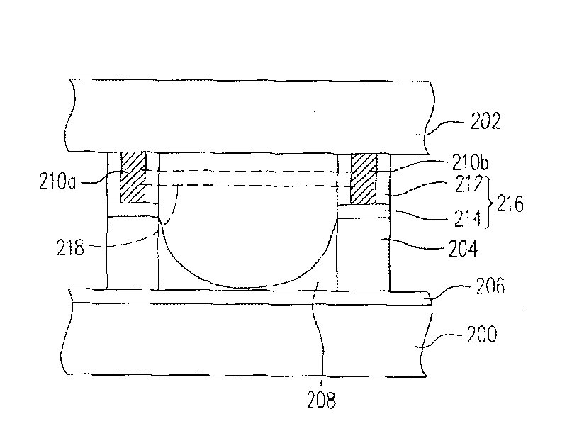
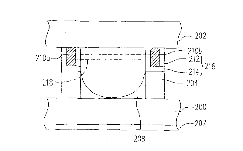
[0052] figure 2 It is a schematic diagram of a planar light source according to an embodiment of the present invention. Please refer to figure 2 The planar light source of this embodiment includes a first substrate 200 , a plurality of barrier walls 204 , a fluorescent layer 208 , a second substrate 202 , a plurality of electrode patterns 210 a , 210 b and an insulating layer 216 .

[0053]The material of the first substrate 200 and the second substrate 202 is, for example, transparent glass. The barrier wall 204 is arranged on the first substrate 200. In one embodiment, the material of the barrier wall 204 includes glass. In addition, the height of the barrier wall 204 For example, it is between 50 and 300 microns. The fluorescent layer 208 is disposed on the surface of the barrier wall 204. In another embodiment, a reflective layer 206 may also be disposed on the surface of the first substrate 200, and the reflective layer 206 may be Make the light generated by the plane...


PUM

PropertyMeasurementUnit
heightaaaaaaaaaa
heightaaaaaaaaaa

Abstract

A method for preparing plane lamp includes setting separation wall on the first base plate and fluorescent layer on surface of separation wall, arranging the second base plate above the first one, setting electrode pattern on the second base plate, aligning each electrode pattern with the first separation wall on the first base plate, covering insulation layer on surface of electrode pattern, filling insert gas between two said base plates and forming discharge circuit between adjacent two electrode patterns above fluorescent layer.

Description

technical field [0001] The invention relates to a light source and a manufacturing method thereof, in particular to a plane light source and a manufacturing method thereof. Background technique [0002] In recent years, liquid crystal display panels (LCD panels) are the mainstream of most display screens. However, since the liquid crystal display panel itself does not have the function of emitting light, a back light module (Back light module) must be provided under the liquid crystal display panel to provide a light source to achieve the display function. The light source in the backlight module is generally provided by a light-emitting tube, and the light emitted by the tube passes through the optical film in the backlight module and is scattered to form a surface light source suitable for illuminating the liquid crystal display panel. [0003] However, if the planar light source can be used directly, the utilization efficiency of light can be improved and a more uniform ...

Claims


Application Information

Patent Timeline
Patent Type & Authority Patents(China)
IPC IPC(8): H01J61/00H01J9/00H01J9/02G02F1/13357
Inventor 张昭仁吴宏伟吕德助许政凯
Owner CPT TECH GRP
Why Eureka
Try Eureka