Position sensor which is intended, in particular, for measuring steering column torsion

A sensor and steering column technology, applied in the field of sensors, can solve problems such as the use of expensive components and low sensitivity of sensors

Active Publication Date: 2007-07-18
MOVING MAGNET TECH
View PDF3 Cites 44 Cited by
  • Summary
  • Abstract
  • Description
  • Claims
  • Application Information

AI Technical Summary

Problems solved by technology

[0021] The object of the present invention is thus to solve the two main problems manifested in the existin

Method used


Image

  • Position sensor which is intended, in particular, for measuring steering column torsion
  • Position sensor which is intended, in particular, for measuring steering column torsion
  • Position sensor which is intended, in particular, for measuring steering column torsion

Examples


Embodiment Construction

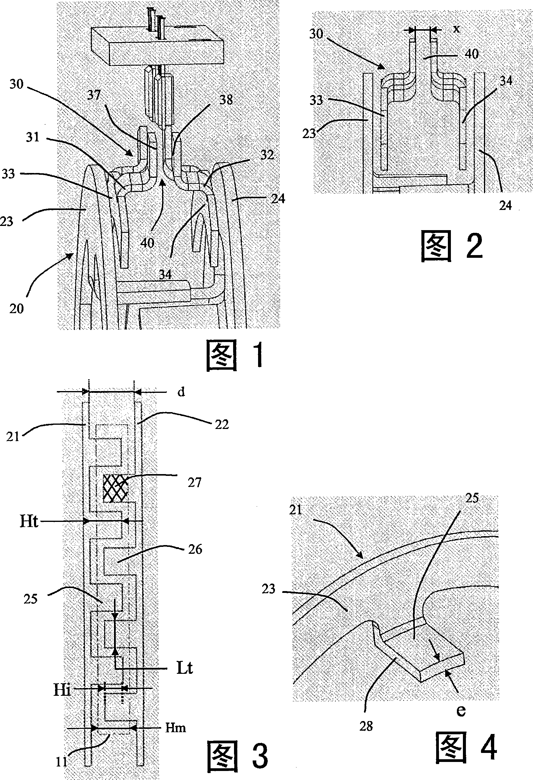
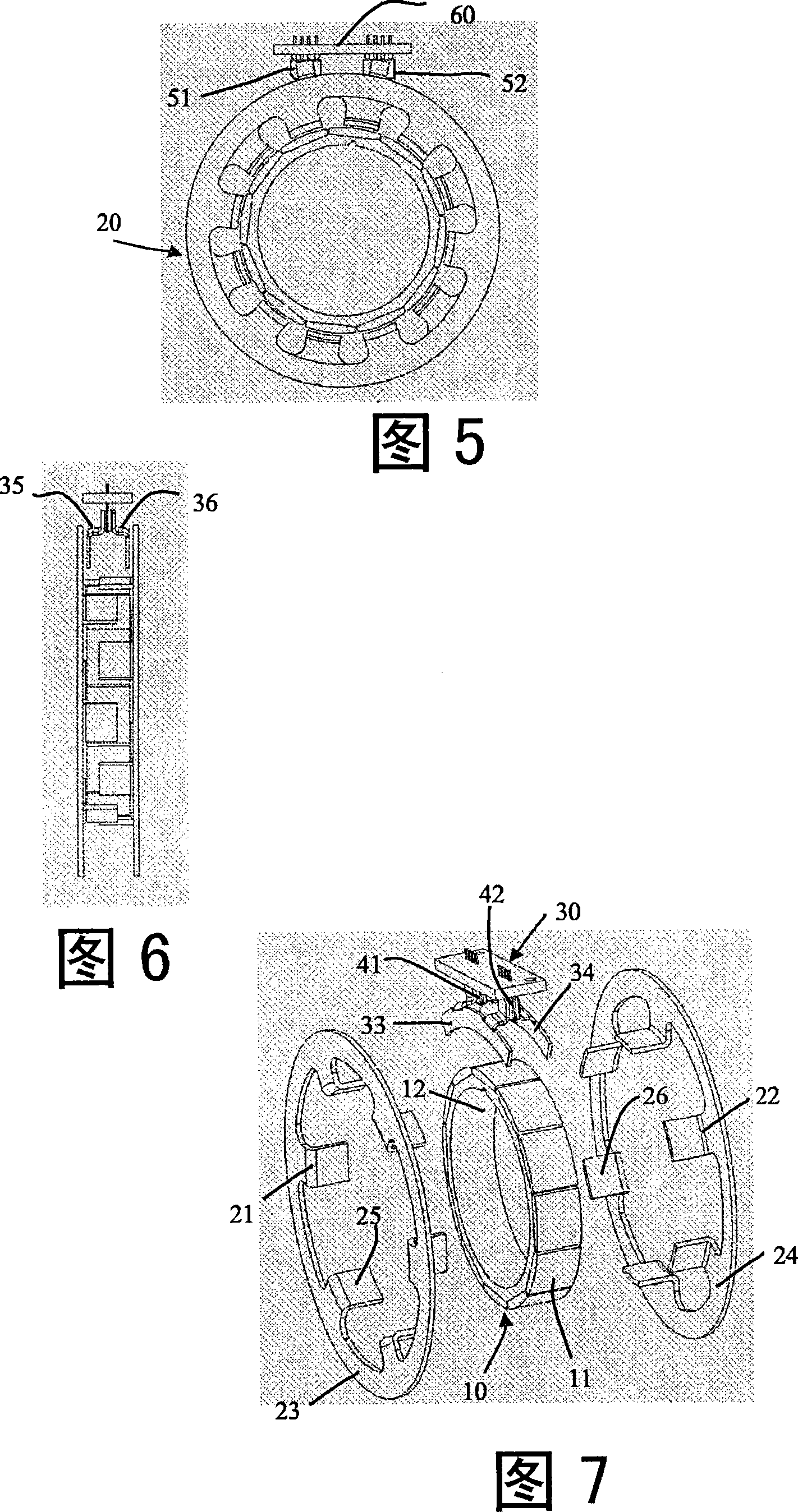
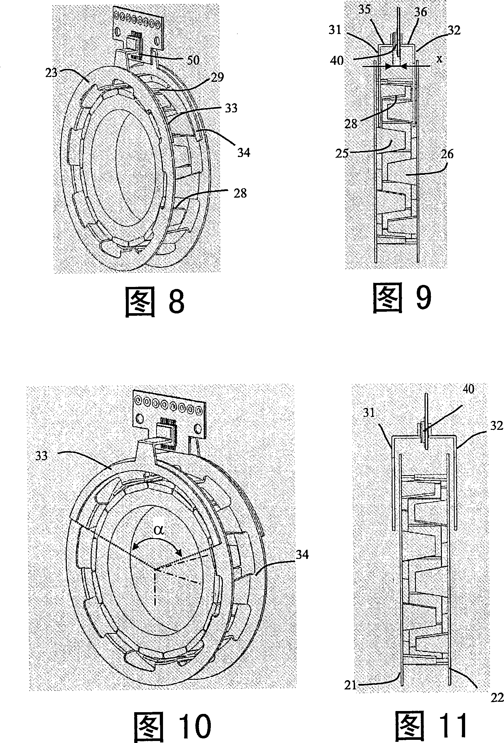
[0083] 1 and 2 are views showing a third magnetic structure of the sensor. The fixed collector structure 30 collects the magnetic flux (magnetic flux) on the stator rings 23 , 24 and concentrates it in the measuring gap 40 .

[0084] The structure comprises two parts 31 , 32 formed respectively by disk-shaped arc segments 33 , 34 configured such that a magnetic flux transmission occurs between the stator and the collecting poles in the axial direction of the sensor.

[0085] The collectors 31 , 32 have arc segments 33 , 34 whose radial width is smaller than the radial width of the stator rings 23 , 24 and which make it possible to tolerate eccentricity defects between the stator structure 20 and the collector structure 30 .

[0086] The collector parts 31 , 32 have a greater offset between the disk-shaped segments 33 , 34 and the surfaces 37 , 38 forming the measuring gap 40 .

[0087] This particular structure makes it possible to limit flux leakage between the collector por...


PUM


Abstract

The invention relates to a position sensor which is intended, in particular, for detecting a steering column torsion. The invention consists of: a first magnetic rotor structure (10) comprising a plurality of radially-oriented magnets; a second stator structure comprising two rings (23, 24) which extend into axially-oriented overlapping teeth (25, 26); and a third fixed collector structure (30) comprising two flux-closing parts which define at least one air gap in which at least one magneto-sensitive element is placed. The invention is characterised in that the flux-closing parts and the stator rings (23, 24) define therebetween a constant collection surface that is independent of the relative radial position of the two structures.

Description

technical field [0001] The present invention relates to the technical field of sensors, and more particularly, but not limited to, a position sensor for measuring the twist of a steering column. Background technique [0002] In the prior art, known from US Patent No. 4984474, a prior art sensor is described having a stator part comprising ferromagnetic parts forming radial teeth, in two stages, Positioned opposite the multi-pole magnets, wherein the multi-pole magnets are radially magnetized in alternating directions. [0003] An additional ferromagnetic component is positioned opposite the stator portion with a gap in which the Hall detectors are positioned. [0004] This prior art solution is not satisfactory, since it leads to a loss of the magnetic signal between the stator part and the part containing the Hall detectors. Furthermore, the magnetic fields generated by the magnets cause losses due to the sensor structure. [0005] The sensor described in French Patent N...

Claims


Application Information

Patent Timeline
IPC IPC(8): G01L3/10G01L5/22
CPCG01L3/104G01L3/10G01L5/22
Inventor 丹尼尔·普鲁丹热拉尔德·马松安托万·富科
Owner MOVING MAGNET TECH
Why Eureka
Try Eureka