Sectionally supported roller core

A technology of segmented support and roll core, applied in the direction of rolls, metal rolling, manufacturing tools, etc., can solve the problems of inability to achieve self-lubrication and low work efficiency

Inactive Publication Date: 2007-07-25
郑红专 +1
View PDF0 Cites 5 Cited by
  • Summary
  • Abstract
  • Description
  • Claims
  • Application Information

AI Technical Summary

Problems solved by technology

[0006] The object of the present invention is to provide a segmented support roll core for a plate and strip mill in view of the above-menti

Method used


Image

  • Sectionally supported roller core
  • Sectionally supported roller core
  • Sectionally supported roller core

Examples


Embodiment Construction

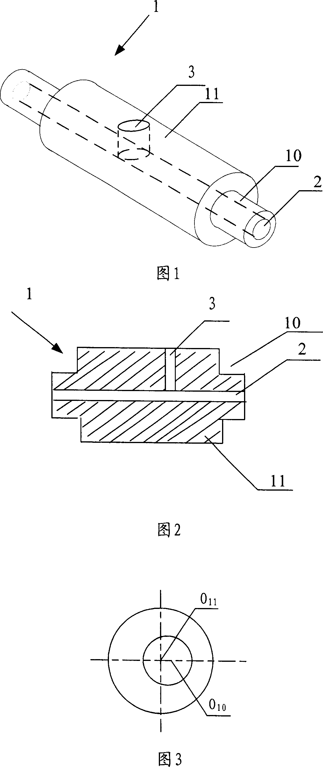
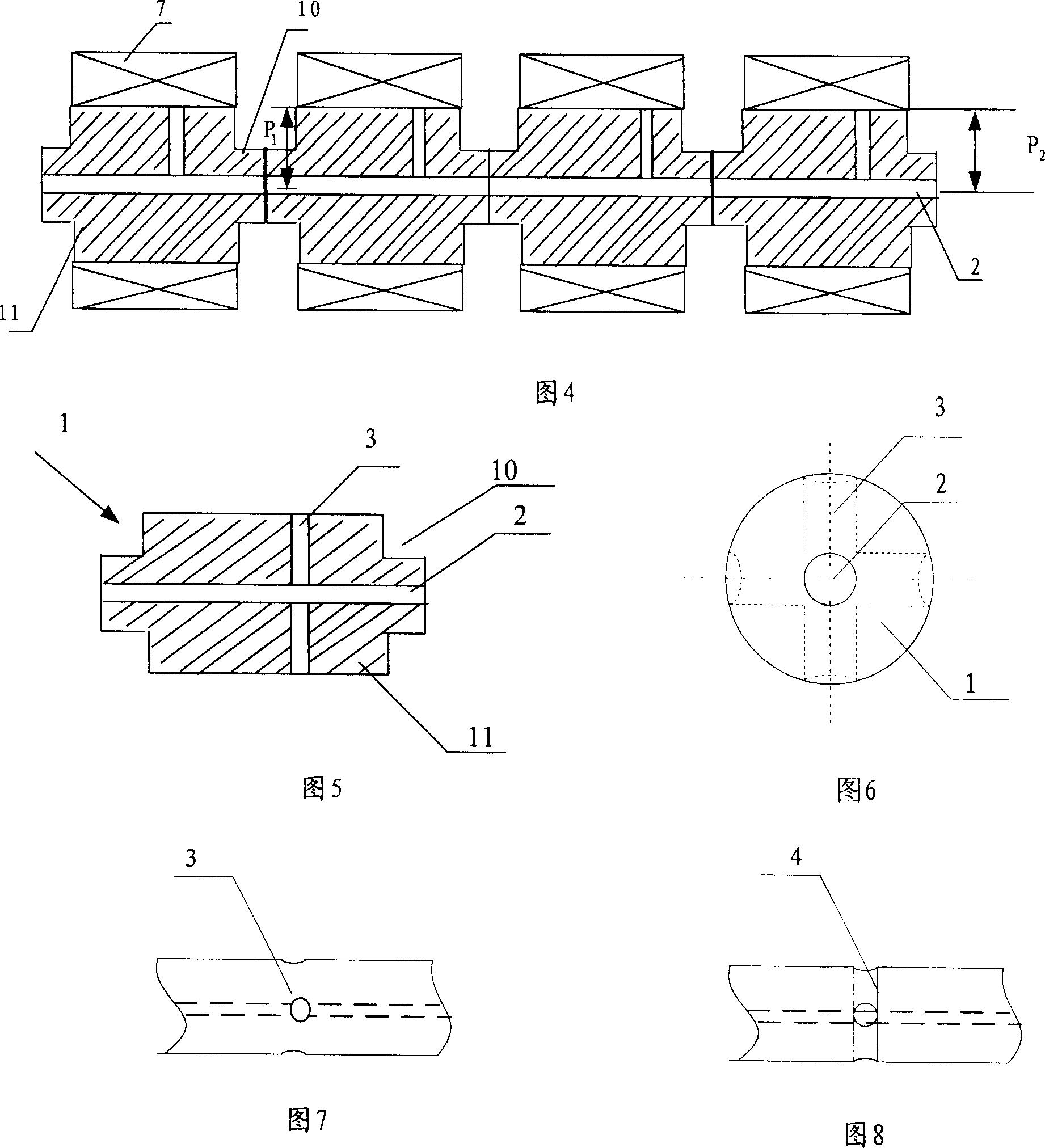
[0031] Fig. 1 is a schematic diagram of the three-dimensional structure of the segmented support roller core of the present invention. Fig. 2 is a schematic view of the longitudinal section of Fig. 1; Fig. 3 is a side view of Fig. 1 . As shown in Fig. 1 and Fig. 2, the present invention segmentally supports the roller core 1, the diameter of the concave platform 10 at both ends of the roller core is smaller than the diameter of the middle part 11 of the segmented roller core, and a concave platform 10 is formed at the two ends of the segmented roller core, so that The segmented support roller core 1 axially runs through a lubricating oil passage 2, and an oil outlet hole 3 is provided outside the segmented roller core, and the oil outlet hole 3 is connected with the lubricating oil passage 2, and the oil outlet hole 3 is arranged on the same side as the roller The bearing connection position where the core phase is socketed, as shown in Figure 3, the concave platform 10 at the...


PUM


Abstract

A segmental supporting mandrel for the rolling roller has an axial lubricating oil channel and two eccentrical ends matched with the baking bearings in eccentrical mode for eliminating the non-uniform deformation of rolling roller.

Description

technical field [0001] The invention relates to a backing roll core, in particular to a segmented support roll core used in a rolling mill. Background technique [0002] In the manufacture and use of plate and strip mills, backing bearing rolls are usually used to support the intermediate support rolls. The existing backing bearing rolls use a through shaft, on which bearings are fixed in sections, and the bearing rolls are The seat direction is embedded in the groove of the convex and concave saddle seat, and is fixedly supported with the saddle seat. [0003] In the prior art, as shown in Figure 11, the original through shaft is divided into multiple sections, and a bearing is installed on each section of the shaft. A concave platform 10 is formed, as shown in FIG. 5 , a groove is formed at the junction of adjacent segmental support roller cores, and a bushing 4 is used to socket together. This kind of roller core is easy to install, flexible to use, easy to replace, and...

Claims


Application Information

Patent Timeline
IPC IPC(8): B21B29/00B21B27/08
Inventor 郑红专赵林珍
Owner 郑红专
Why Eureka
Try Eureka