Supercharge Your Innovation With Domain-Expert AI Agents!

Structure for fixing lever switch

A technology of lever switch and assembly structure, applied in the direction of electric switch, signal device, transportation and packaging, etc., can solve the problems of assembly, parts management, parts handling trouble, etc., and achieve the effect of easy assembly and restraint of the influence of force

Inactive Publication Date: 2007-07-25
NILES PARTS CO LTD
View PDF2 Cites 5 Cited by
  • Summary
  • Abstract
  • Description
  • Claims
  • Application Information

AI Technical Summary

Problems solved by technology

[0010] However, in this case, before the turn signal light switch 101, the wiper switch 103 and the rotary connector 121 are assembled on the side of the steering column 127, they must be separately operated, and assembly, parts management, and parts transportation may become troublesome.

Method used


Image

  • Structure for fixing lever switch
  • Structure for fixing lever switch
  • Structure for fixing lever switch

Examples


Embodiment 1

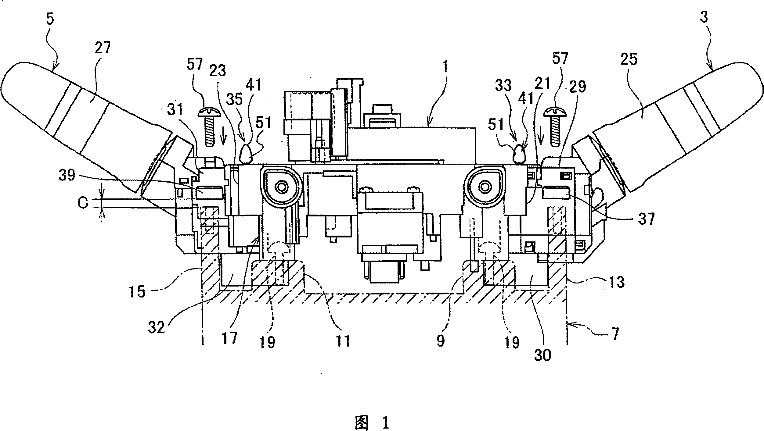
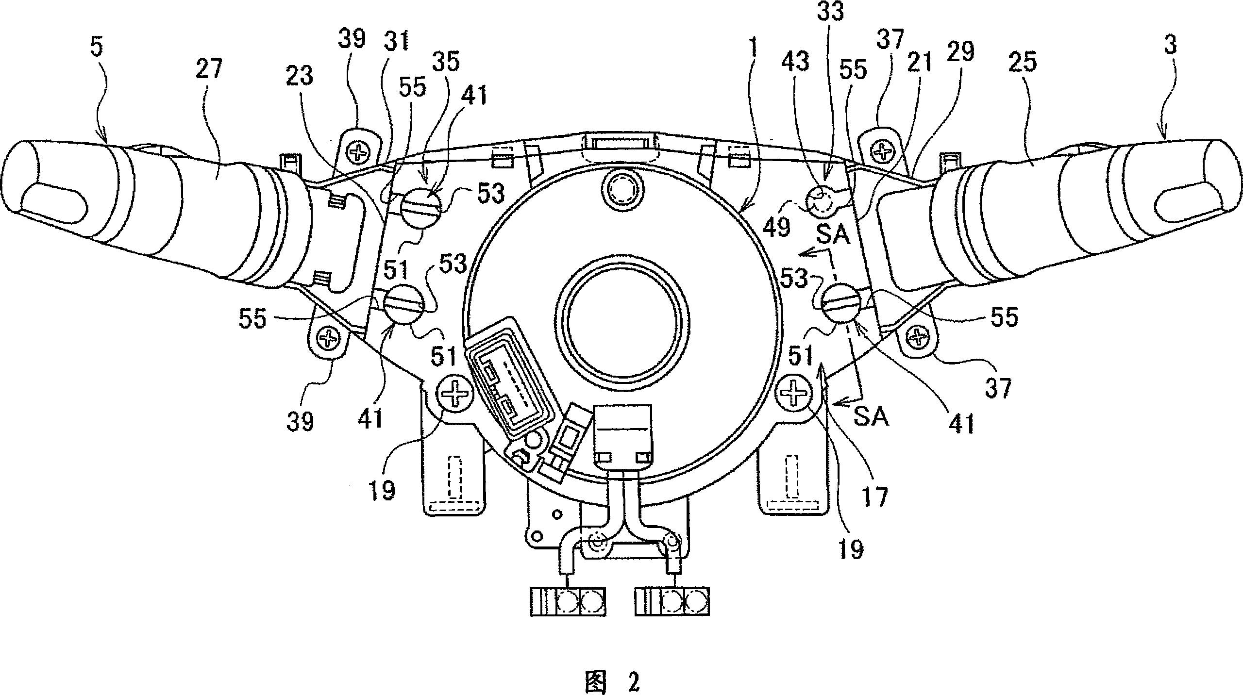
[0024] Fig. 1 and Fig. 2 are side views showing the combined switch device applicable to the relationship between the lever switch and the rotary connector in Embodiment 1 of the present invention, and Fig. 2 is its plan view. As shown in Fig. 1 and Fig. 2, the rotary connector 1, the turn signal light switch 3 as a lever switch and the wiper switch 5 are configured to be assembled on the assembly handle 7 together.

[0025] The aforementioned assembly handle 7 includes connector assembly seats 9 and 11 as connector assembly parts fixed on one side of the steering column, and switch assembly parts 13 and 15 as switch assembly parts. The connector mounts 9 and 11 are provided at, for example, two places, and the switch mounts 13 and 15 are provided at two places, for example, on the side of the lever switch 3 and the side of the wiper switch 5 , respectively.

[0026] The aforementioned rotary connector 1 is fixedly assembled on the aforementioned connector assembly seats 9 , 1...


PUM


Abstract

A structure for fixing a lever switch in which the effect of a force on the rotary connector side due to an undue input from a turn signal switch or a wiper switch can be suppressed in a fixed state while enabling subassembly of the rotary connector, the turn signal switch, and the wiper switch. The lever switch fixing structure comprises temporary fixing means (33, 35) for engaging the turn signal switch (3) and the wiper switch (5) with the rotary connector (1) temporarily before fixing them, and tightening tongue parts (37, 39) provided to the turn signal switch (3) and the wiper switch (5) and facing switch fixing seats (13, 15) with a gap (C) therebetween when the rotary connector (1) is fixed to connector fixing seats (9, 11) in the temporarily engaged state. The structure is characterized in that the temporary fixing means (33, 35) disengage when the tightening tongue parts (37, 39) are moved together with the signal switch (3) and the wiper switch (5) in the direction in which the gap (C) is eliminated and coupled with the switch fixing seats (13, 15).

Description

technical field [0001] The present invention relates to an assembly structure of lever switches such as turn signal lamp switches and wiper switches of automobiles. Background technique [0002] As an assembly structure of the conventional lever switch, for example, it is as shown in FIG. 5 . The lever switch shown in FIG. 5 includes, for example, a turn signal light switch 101 and a wiper switch 103 . [0003] The turn signal light switch 101 and the wiper switch 103 are fitted in the switch assembly openings 107 , 109 of the base 105 respectively, and are fixed to the base 105 by elastically engaging each engaging claw 111 on one side of the base 105 . In the base 105 are provided a connecting portion 113 and an engaging claw 115 . Also, insertion holes 117 are provided in the base 105, and engaging pawls 119 are provided inside the insertion holes 117, respectively. In the rotary connector 121, a connecting piece portion 123 and an engaging foot portion 125 are provide...

Claims


Application Information

Patent Timeline
Patent Type & Authority Applications(China)
IPC IPC(8): H01H9/02B60R16/02B62D1/04H01H25/04
CPCB60Q1/1461H01H9/02H01H25/04B60R16/02B62D1/04
Inventor 内山则夫
Owner NILES PARTS CO LTD
Features
  • R&D
  • Intellectual Property
  • Life Sciences
  • Materials
  • Tech Scout
  • Unparalleled Data Quality
  • Higher Quality Content
  • 60% Fewer Hallucinations
Learn More