Receptacle of electrical connector

a technology of electrical connectors and receptacles, which is applied in the direction of coupling devices, two-part coupling devices, electrical apparatus, etc., can solve the problems of high repair cost, easy damage to elastic terminals or the tongue of plastic bodies, radio frequency interference, etc., and achieve the effect of preventing the expensive cost of repairing a damaged receptacl

Active Publication Date: 2016-03-08
ADVANCED CONNECTEK INC
View PDF15 Cites 11 Cited by
  • Summary
  • Abstract
  • Description
  • Claims
  • Application Information

AI Technical Summary

Benefits of technology

[0005]The present invention provides a receptacle for an electrical connector, in which a plurality of terminals and a tongue for a plastic body are minimally damaged, to prevent expensive cost of repairing a damaged receptacle.
[0006]According to disadvantages in the prior art, the present invention also provides a plug matching the receptacle for the electrical connector set forth. Shielding structures of housings of the receptacle and the plug have a better design and cause minimal radio frequency interference, to prevent interference between devices.
[0024]The tongues of the plastic bodies of the receptacles of the electrical connector of the present invention, i.e. the first tongue part of the first plastic body and the second tongue part of the second plastic body, are close to the upper side and to the lower side of the metal housing body, and to the terminals of the receptacle, i.e. the first flat terminals and the second flat terminals, have a flat shape. Therefore, the damage to the receptacle due to abnormal usage, such as plugging a plug in an unmatched receptacle, rarely happens, to prevent the expensive cost of repairing a damaged receptacle.

Problems solved by technology

The elastic terminals or the tongue of the plastic body are easily damaged due to abnormal usage, such as plugging the plug in a receptacle that does not match.
Therefore, a cost for repair is high.
The shielding structures of the housings of the receptacle and the plug of the USB connectors have a poor design and easily cause radio frequency interference.
When radio frequency interference happens, devices like wireless mouses or blue tooth gadgets do not function properly.

Method used


Image

  • Receptacle of electrical connector
  • Receptacle of electrical connector
  • Receptacle of electrical connector

Examples


Embodiment Construction

[0037]In the embodiments below, the same or similar reference characters represent the same or similar components. In addition, directional terms described in the embodiments are merely used for reference and illustration according to the drawings. Therefore, the directional terms shall not limit the scope of the invention.

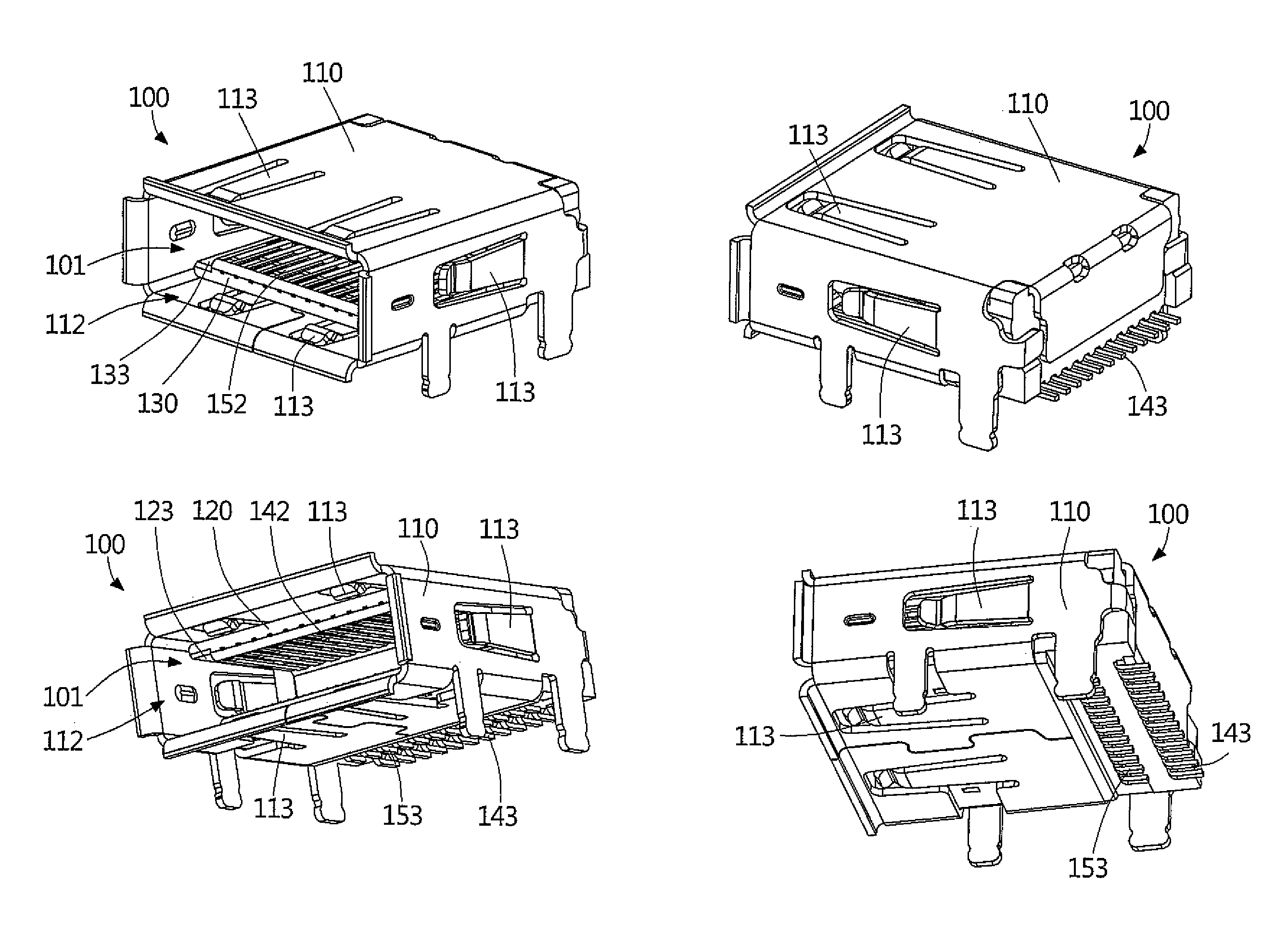
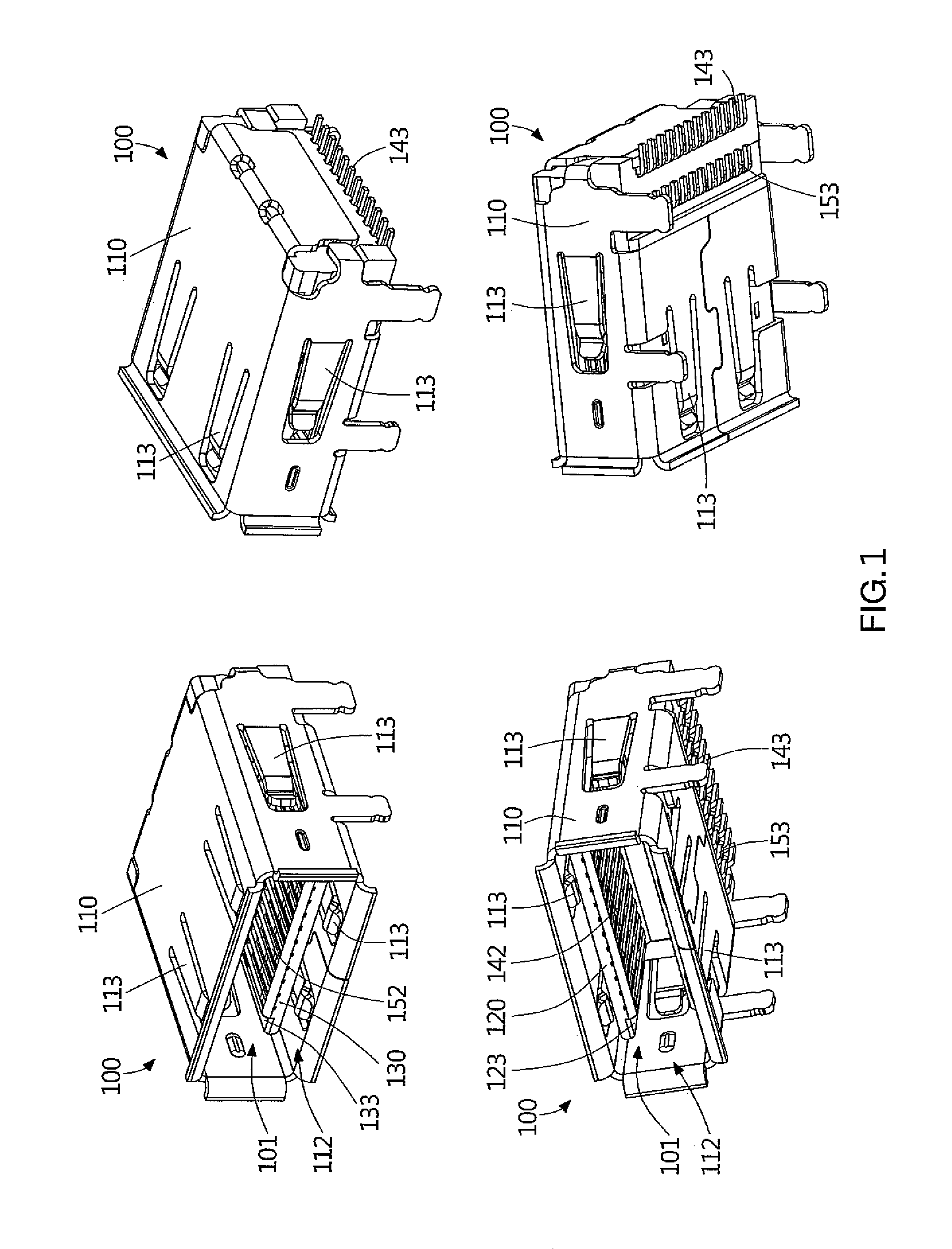
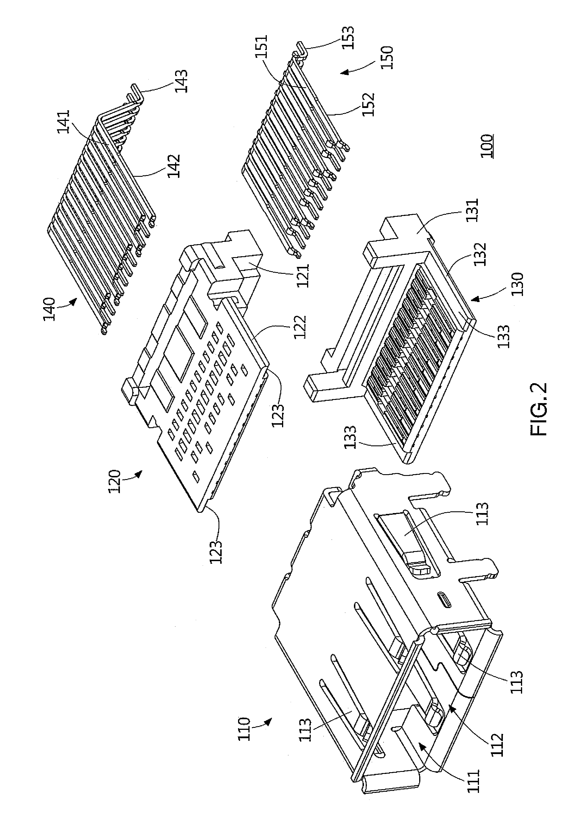
[0038]As shown in FIG. 1 to FIG. 3, a receptacle 100 of an electrical connector according to the first embodiment of the invention comprises a metal housing body 110, a plastic main body, and a plurality of flat terminals. The plastic main body comprises, but is not limited to, a first plastic body 120 and a second plastic body 130. In another embodiment, a plastic main body can be formed as a one-piece component, instead of being formed by connecting the first plastic body 120 to the second plastic body 130. The flat terminals comprise a plurality of first flat terminals 140 and a plurality of second flat terminals 150. The metal housing body 110 comprises an acc...


PUM


Abstract

A receptacle for an electrical connector includes a metal housing body, a plastic main body positioned in the metal housing body, and flat terminals. The plastic main body incorporates with the metal housing body to form an accommodating space for being plugged into by a plug. First and second tongue parts disposed on the plastic main body are respectively close to upper and lower sides of the metal housing body. Each flat terminal includes a fixing part, a contacting part formed in a flat shape, and a soldering part. The contacting parts are respectively disposed on first and second tongue parts and respectively are exposed to the accommodating space in downward and upward directions. A tongue of a plastic body of the receptacle, i.e. first and second tongue parts, and the flat terminals are thus minimally damaged, to prevent the expensive cost of repairing a damaged receptacle.

Description

BACKGROUND OF THE INVENTION[0001]1. Field of the Invention[0002]The present invention relates to an electrical connector and, more particularly, to a receptacle for an electrical connector and a plug matching the same. In general, a receptacle and a plug for an electrical connector are also known as a receptacle connector and a plug connector.[0003]2. Description of the Prior Art[0004]Either a receptacle or a plug of an electrical connector, e.g. a universal serial bus (USB) connector matching the standard USB 3.0, comprises a plastic body with a tongue, flat terminals (i.e. each terminal comprise a contacting part utilized for contacting another terminal and having a flat shape), and elastic terminals (i.e. each terminal comprise a contacting part utilized for contacting another terminal and having an elastic arm shape). The elastic terminals or the tongue of the plastic body are easily damaged due to abnormal usage, such as plugging the plug in a receptacle that does not match. A ...

Claims


Application Information

Patent Timeline
Patent Type & Authority Patents(United States)
IPC IPC(8): H01R24/00H01R12/72H01R13/405H01R13/514H01R12/70H01R24/60H01R13/6594
CPCH01R12/707H01R12/724H01R13/405H01R13/514H01R13/6594H01R24/60
Inventor HOU, PIN-YUANKAO, YA-FENTSAI, YU-LUNWANG, WEN-YUTSAI, WEN-HSIEN
Owner ADVANCED CONNECTEK INC
Why Eureka
Try Eureka