
Apparatus and method for space-time-frequency block coding for increasing performance

A frequency block and coding scheme technology, applied in the field of performance devices, can solve the problems of low execution efficiency of orthogonal space-time codes and the like

Active Publication Date: 2007-07-25
SAMSUNG ELECTRONICS CO LTD
View PDF0 Cites 21 Cited by
  • Summary
  • Abstract
  • Description
  • Claims
  • Application Information

AI Technical Summary

Problems solved by technology

In this system, the OFCs perform less efficiently, which means that there is more room for improving the performance of the OFCs in

Method used

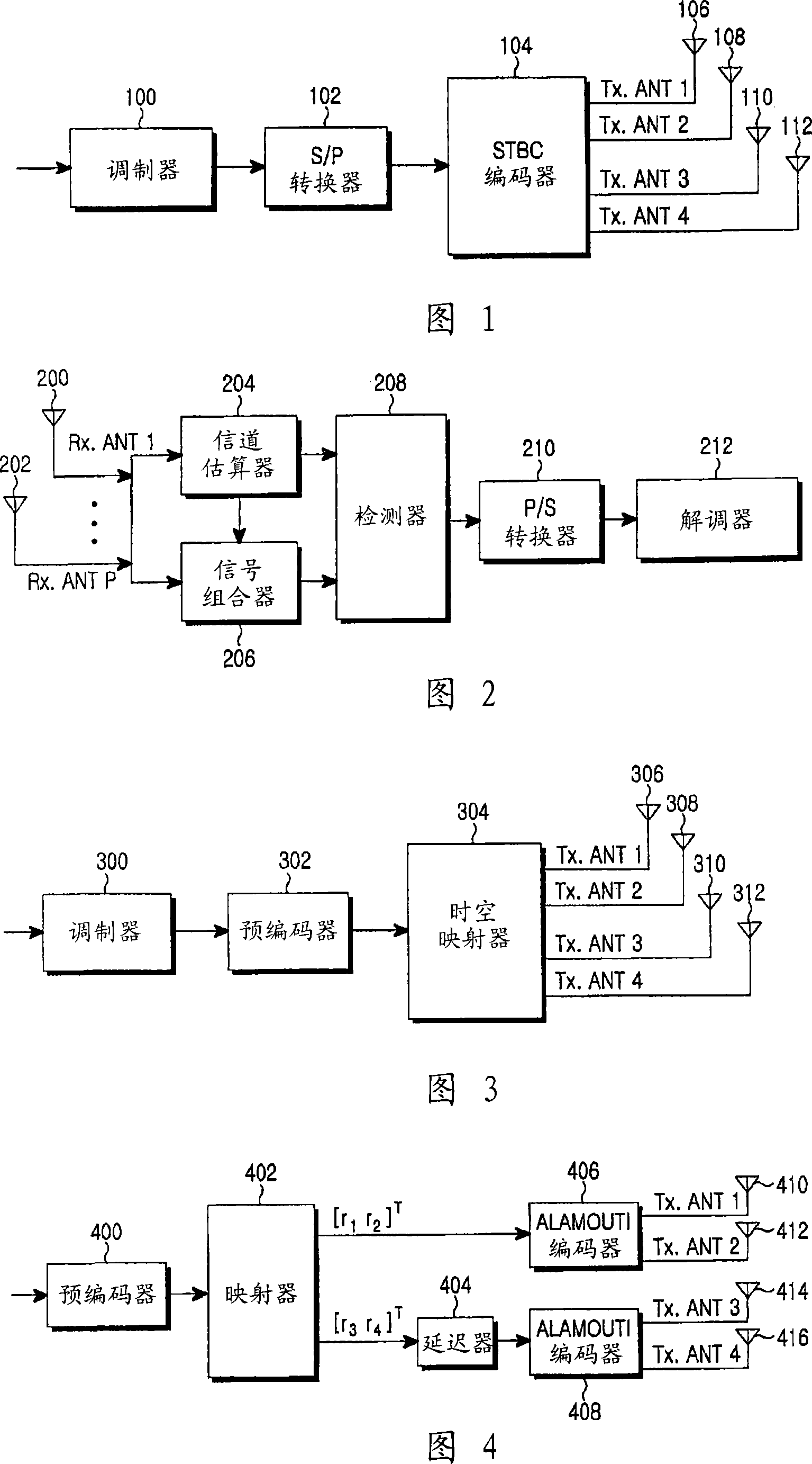
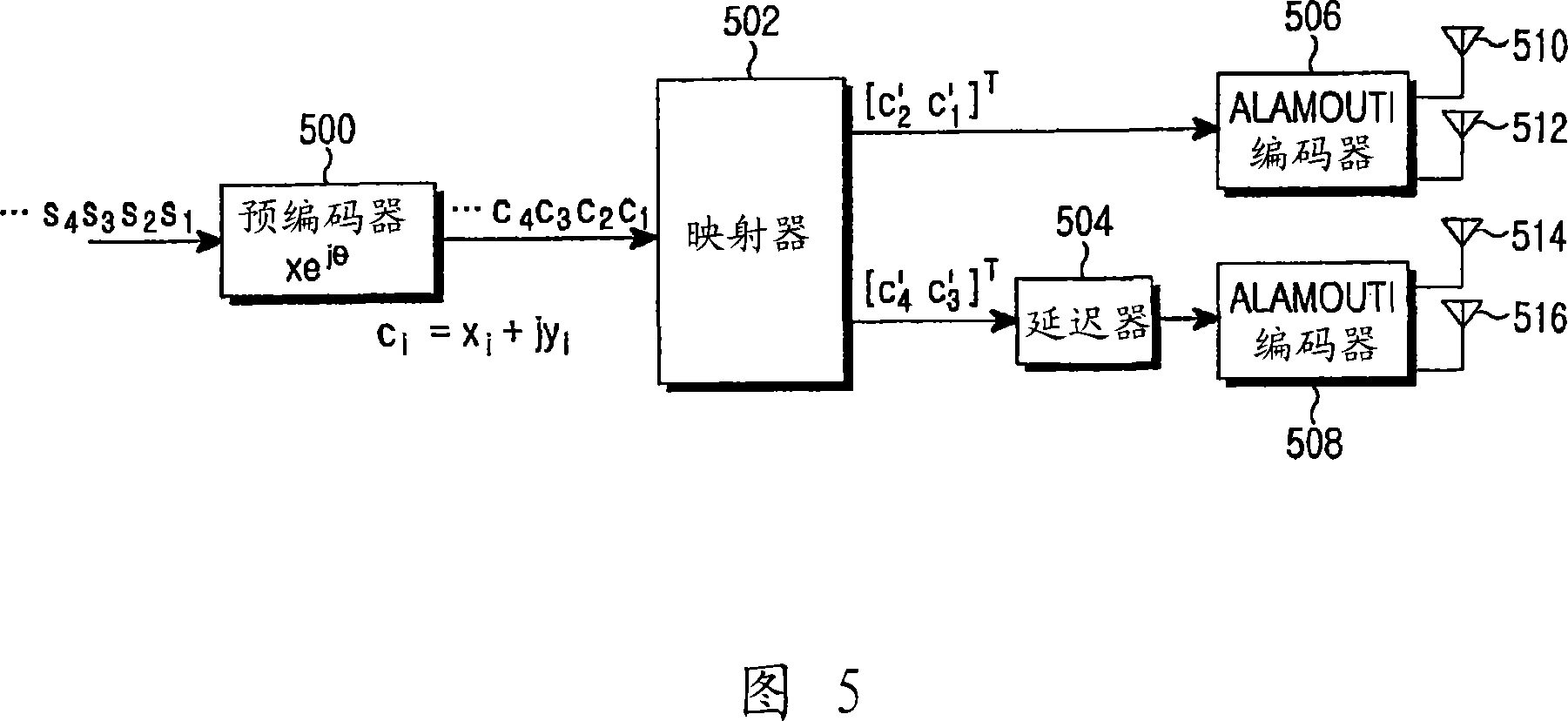

Image

  • Apparatus and method for space-time-frequency block coding for increasing performance
  • Apparatus and method for space-time-frequency block coding for increasing performance
  • Apparatus and method for space-time-frequency block coding for increasing performance

Examples


Embodiment Construction

[0082] Hereinafter, preferred embodiments of the present invention will be described in detail with reference to the accompanying drawings. In the following description, well-known functions or constructions are not described in detail since they would obscure the invention in unnecessary detail.

[0083] It is an object of the present invention to provide a space-time-frequency block coding scheme for improving performance in systems using FDFR orthogonal STFBC.

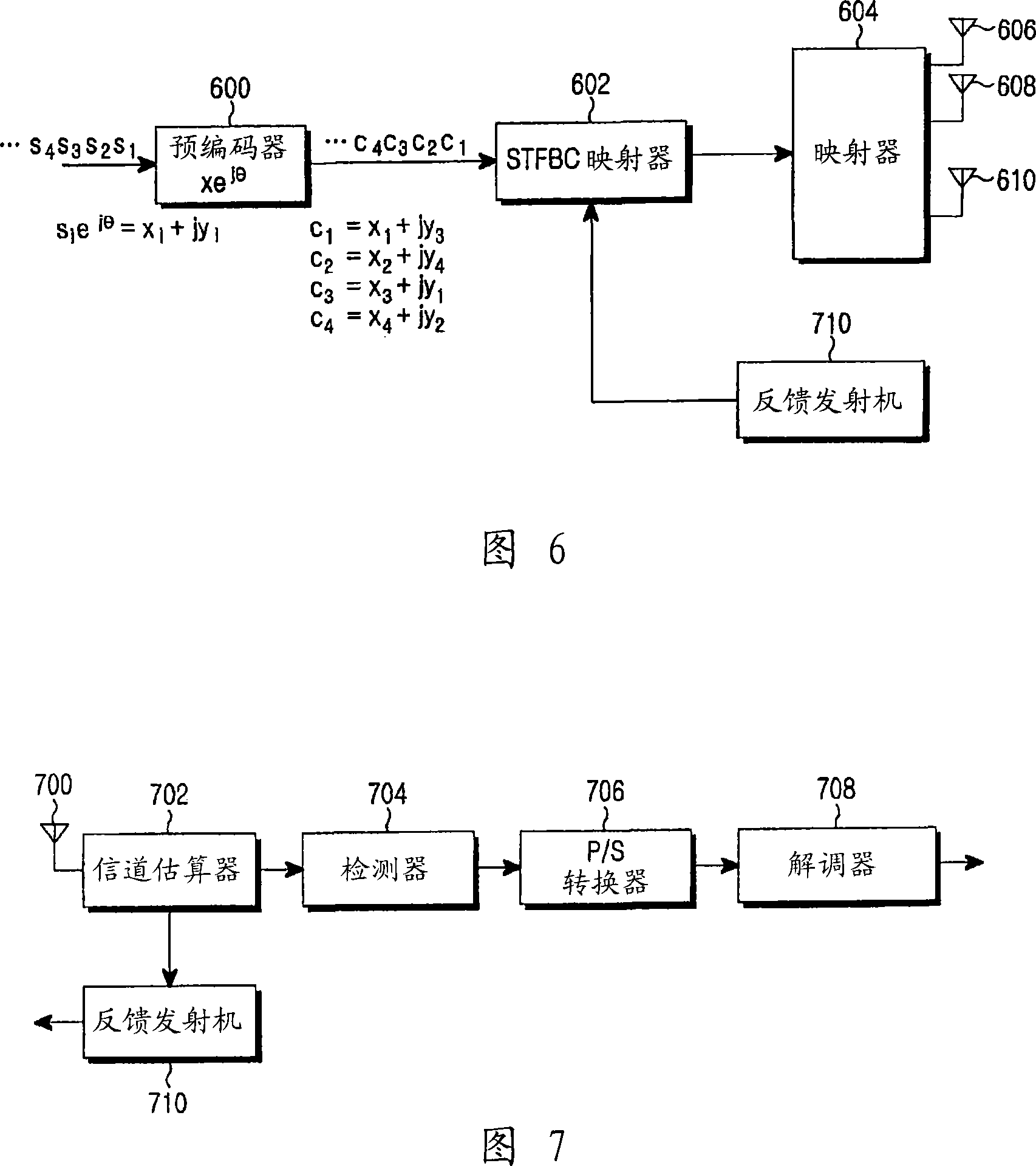
[0084] FIG. 6 is a block diagram of a transmitter in a mobile communication system using the STFBC scheme using feedback information from a receiver. This embodiment is explained as an example having very similar effects corresponding to the present invention. Here, it is assumed that the transmitter uses three Tx antennas.

[0085] Referring to Fig. 6, the precoder 600 will input the information symbol s 1 , s 2 , s 3 , s 4 each of which is multiplied by e jθ , that is, s in the complex plane 1 , s 2 , s ...


PUM


Abstract

A space-time-frequency block coding apparatus and method in a transmitter with three transmit (Tx) antennas are provided. An input symbol sequence is transmitted through three Tx antennas according to a permutation method using a selected transmission matrix in order to improve the performance of an STFBC.

Description

technical field [0001] The present invention relates generally to a space-time-frequency block coding arrangement in a transmitter with three transmit (Tx) antennas, and more particularly to transmitting an input symbol sequence through three Tx antennas using a selected transmission matrix in order to improve a space-time-frequency block code (STFBC) performance device. Background technique [0002] The fundamental problem in communication is how to efficiently and reliably transmit data over a channel. Since the next generation of multimedia mobile communication requires a high-speed communication system capable of transmitting various information including video and wireless data in addition to focusing on voice services, it is important to enhance system efficiency. [0003] In a wireless channel environment of a mobile communication system, contrary to a wired channel environment, a transmission signal inevitably suffers loss due to several factors such as multipath i...

Claims


Application Information

Patent Timeline
IPC IPC(8): H04B7/06
CPCH04L1/0625H04L1/0643H04L1/0668H04L1/0681
Inventor 蔡赞秉尹圣烈郑鸿实卢元一朴东植金宰烈吴廷泰高均秉
Owner SAMSUNG ELECTRONICS CO LTD
Learn More