Scheduling with delayed graphs for communication networks

a communication network and graph technology, applied in the field of data transfer scheduling, can solve the problems of inefficient resource utilization, high equipment cost of network cost, and high cost of network cost of grooming devices

Inactive Publication Date: 2009-02-10
WSOU INVESTMENTS LLC +1
View PDF19 Cites 23 Cited by
  • Summary
  • Abstract
  • Description
  • Claims
  • Application Information

AI Technical Summary

Problems solved by technology

One problem associated with WDM optical rings is that the granularity of traffic demands is determined by the wavelength granularity, which leads to inefficient resource utilization.
Although the number of separate wavelength transmitters and / or receivers can be reduced with electronic grooming as opposed to optical grooming, grooming devices add to the network cost.
This network cost can be high in terms of equipment cost, added cost of controlling additional devices, sparing, and network management support.
When the data from two transmitters arrives at the same receiver, a conflict arises and data is corrupted at the receiver.
Propagation delay may cause packets on a given wavelength sent from nodes distant to a given node to overlap packets that are sent from nearer nodes which the given node is attempting to receive.
The contention illustrated in FIGS. 1A, 1B, and 1C shows that simple scheduling, such as is typically defined in TDMA networks, does not provide 100% throughput in a TTFR ring with large propagation delays.

Method used


Image

  • Scheduling with delayed graphs for communication networks
  • Scheduling with delayed graphs for communication networks
  • Scheduling with delayed graphs for communication networks

Examples


Embodiment Construction

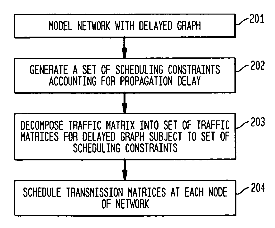
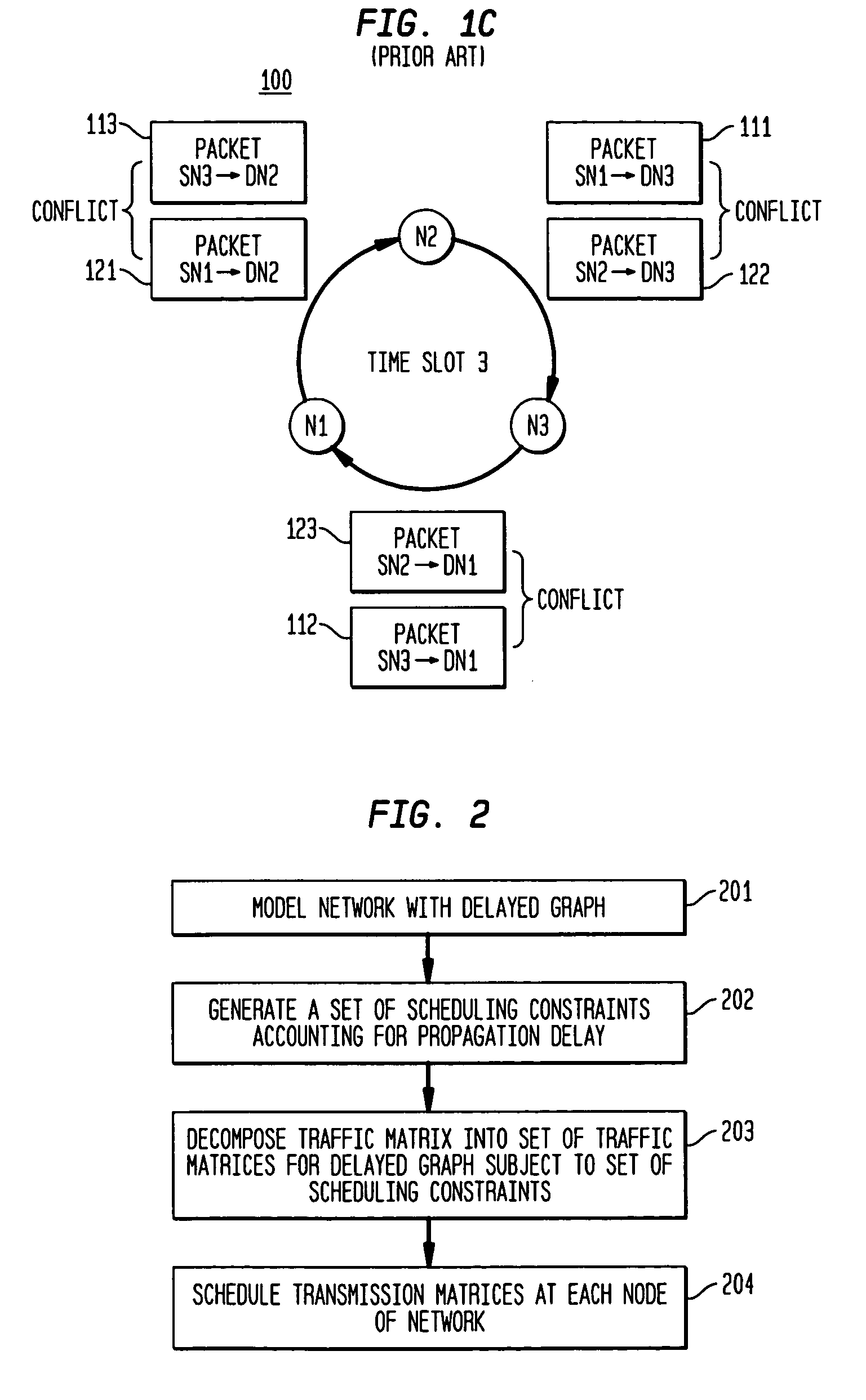
[0034]FIG. 2 shows an exemplary method 200 of generating a network schedule accounting for propagation delay in accordance with the present invention. Exemplary method 200 might be employed in a scheduler of a node in a communications network. The communications network might be a packet- or burst-switched transport network, and the communications network might be either i) a network of electronic switches / routers or ii) optical switches that are connected either with wired or optical links. The communications network as described herein is configured as a ring network, although the present invention may be extended to other types of network configurations that may be modeled with a ring network accounting for delays in accordance with an exemplary embodiment of the present invention.

[0035]At step 201, the network is modeled with a delayed graph, and the network has a corresponding rate matrix that characterizing traffic demands through the network. At step 202, a set of scheduling ...


PUM


Abstract

A network of nodes interconnected by links, such as a wavelength division multiplexing (WDM) ring network, is modeled by a delayed graph in which propagation delay between nodes is accounted for. Given the delayed graph, a traffic matrix for an admissible traffic pattern is scheduled over a frame period. Scheduling of the traffic matrix formulates a set of scheduling constraints based on the delays and decomposes the traffic matrix into a set of transmission matrices. Each of the set of transmission matrices is scheduled over the frame period.

Description

BACKGROUND OF THE INVENTION[0001]1. Field of the Invention[0002]The present invention relates to scheduling data transfer between nodes in a communications network, and, more particularly, to generating a schedule using graphs.[0003]2. Description of the Related Art[0004]Wavelength Division Multiplexing (WDM) is commonly employed for optical transport networks. WDM technology is applied to both optical ring architectures and mesh networks. A transport WDM optical ring consists of a number N of nodes connected through optical links in a ring topology. Each node can add or drop one or more wavelengths, and each node passes-through the rest of the wavelengths. In many WDM systems, a dedicated wavelength is assigned between any two nodes requiring a communication path, and traffic management is performed with wavelength granularity.[0005]The cost of each WDM node is determined by: i) the number of optical transmitters and receivers corresponding to the number of wavelengths that are add...

Claims


Application Information

Patent Timeline
Patent Type & Authority Patents(United States)
IPC IPC(8): G01R31/08H04L12/28H04L12/56
CPCH04L12/5693H04L47/10H04L47/52H04L47/50
Inventor KESLASSY, ISAACKODIALAM, MURALIDHARAN S.LAKSHMAN, TIRUNELL V.STILIADIS, DIMITRIOS
Owner WSOU INVESTMENTS LLC
Why Eureka
Try Eureka