Sphygmomanometer

一种血压计、血压的技术,应用在血压计领域,能够解决使用不是很方便、血压计规模变大等问题,达到尺寸小型化、使用方便的效果

Active Publication Date: 2007-08-01
TERUMO KK
View PDF3 Cites 7 Cited by
  • Summary
  • Abstract
  • Description
  • Claims
  • Application Information

AI Technical Summary

Problems solved by technology

[0007] However, in the sphygmomanometers described in Patent Documents 1 and 2, since the balloon is connected to the cuff or the main body of the sphygmomanometer through an air tube, it is necessary to hold the main body with one hand and hold the main body with the other hand. It is not very convenient to use by keeping the delivery balloon for pressurization
[0008] In addition, as in the sphygmomanometers described in Patent Documents 1 and 2, there is also a problem that the overall scale of the sphygmomanometer becomes larger by connecting each unit through a tube.

Method used


Image

  • Sphygmomanometer
  • Sphygmomanometer
  • Sphygmomanometer

Examples


Embodiment Construction

[0044] Hereinafter, embodiments of the present invention will be described in detail with reference to the drawings.

[0045]

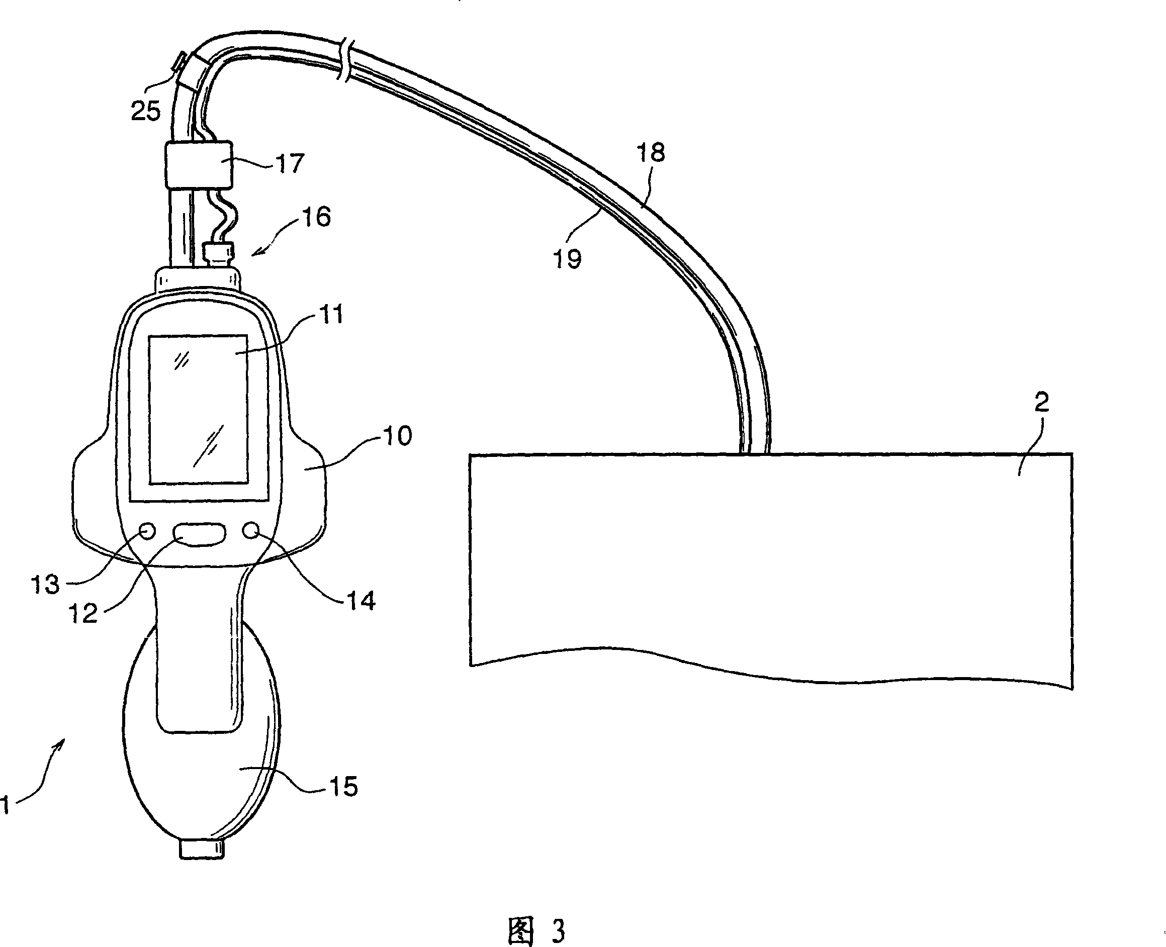
[0046] FIG. 3 is a diagram showing the appearance of the sphygmomanometer 1 and the cuff 2 thereof in the present embodiment.

[0047] In FIG. 3 , reference numeral 10 denotes a box of the sphygmomanometer main body, and a circuit board and piping (described later) are housed inside. The cuff 2 (including a large cuff (large-capacity air bag) 22 and a small cuff 23 (small-capacity air bag) described later) sends air and exhausts it from the cuff 2 . Reference numeral 11 denotes a display unit on which the maximum and minimum blood pressure values, pulse rate, measurement mode, and the like are displayed. Symbol 12 denotes a switch for switching the power supply, and symbol 13 denotes a mode switch. The sphygmomanometer 1 in the present embodiment includes a plurality of modes, ie, a normal mode, a slow mode, and an auscultation mode (three types) ...


PUM


Abstract

An easy-to-handle sphygmomanometer used to measure a blood pressure based on the vibration of an artery wall caused by artery pulsation due to a variation in pressure of a cuff. The sphygmomanometer comprises a cuff band connected to a sphygmomanometer body through a tube, a display part for displaying the measured results of blood pressure, and an air feed part detachable from the sphygmomanometer body and feeding air to the cuff band for pressurization. The air feed part is threaded to the sphygmomanometer body by a thread structure, and maintains its threaded state by a crimping ring. Also, the air feed part comprises a filter for preventing dirt from entering the sphygmomanometer body.

Description

technical field [0001] The invention relates to a sphygmomanometer used by nurses and other medical practitioners in hospitals and other places to measure blood pressure of patients, in particular to a sphygmomanometer which is portable and can choose various cuffs. Background technique [0002] For example, Patent Documents 1 and 2 disclose a sphygmomanometer that sends air pressurized by a balloon (rubber ball) to a cuff via a sphygmomanometer main body. [0003] FIG. 1 shows a sphygmomanometer having a Korotkoff sound sensor disclosed in Patent Document 1. As shown in FIG. In the sphygmomanometer shown in FIG. 1 , a main body 1301 and a cuff 1302 are connected through a rubber tube 1304 and a lead wire 1305 . In addition, a rubber ball 1303 for feeding air is connected to the cuff 1302 . [0004] In addition, FIG. 2 shows a sphygmomanometer disclosed in Patent Document 2. As shown in FIG. In this sphygmomanometer, there is a flexible first air tube 1405 and a second ai...

Claims


Application Information

Patent Timeline
Patent Type & Authority Applications(China)
IPC IPC(8): A61B5/022
CPCA61B5/02225A61B5/02116A61B5/02233A61B5/022
Inventor 望月宽
Owner TERUMO KK
Why Eureka
Try Eureka