New type automatic exhaust steam valve

An automatic exhaust valve, a new type of technology, applied in the direction of valve lift, valve details, valve device, etc., can solve the problems of poor sealing performance, failure to achieve the purpose of exhaust, short life, etc., to improve the exhaust capacity and facilitate the valve Sealing, the effect of improving sealing performance

Inactive Publication Date: 2007-08-08
浙江世进水控股份有限公司
View PDF0 Cites 5 Cited by
  • Summary
  • Abstract
  • Description
  • Claims
  • Application Information

AI Technical Summary

Problems solved by technology

Although the structure is simple, the effect obtained is not ideal. The exhaust is unstable when exhausting, and the gas in the cavity cannot be completely exhausted. The sealing performance is poor, the life is short, the ope

Method used


Image

  • New type automatic exhaust steam valve
  • New type automatic exhaust steam valve
  • New type automatic exhaust steam valve

Examples


Embodiment Construction

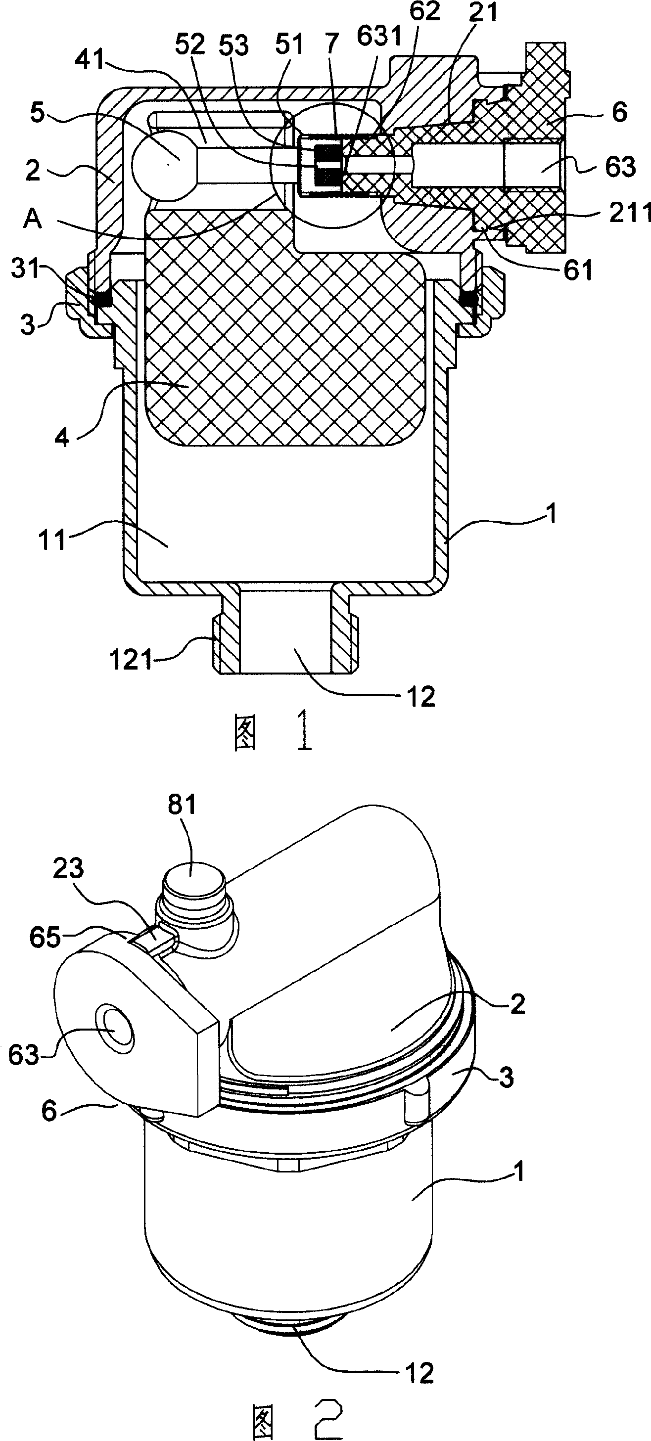
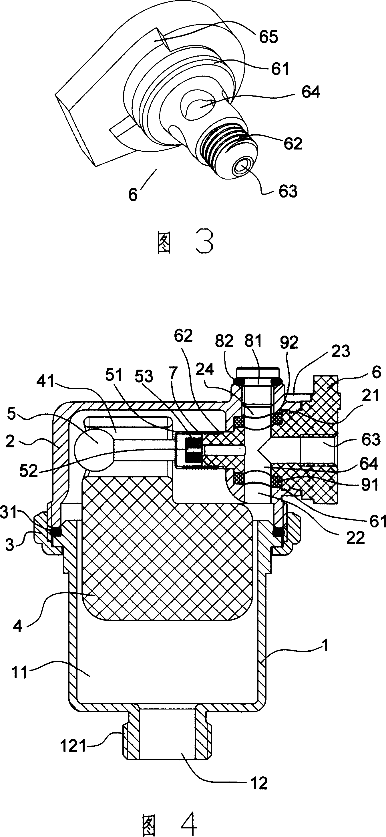
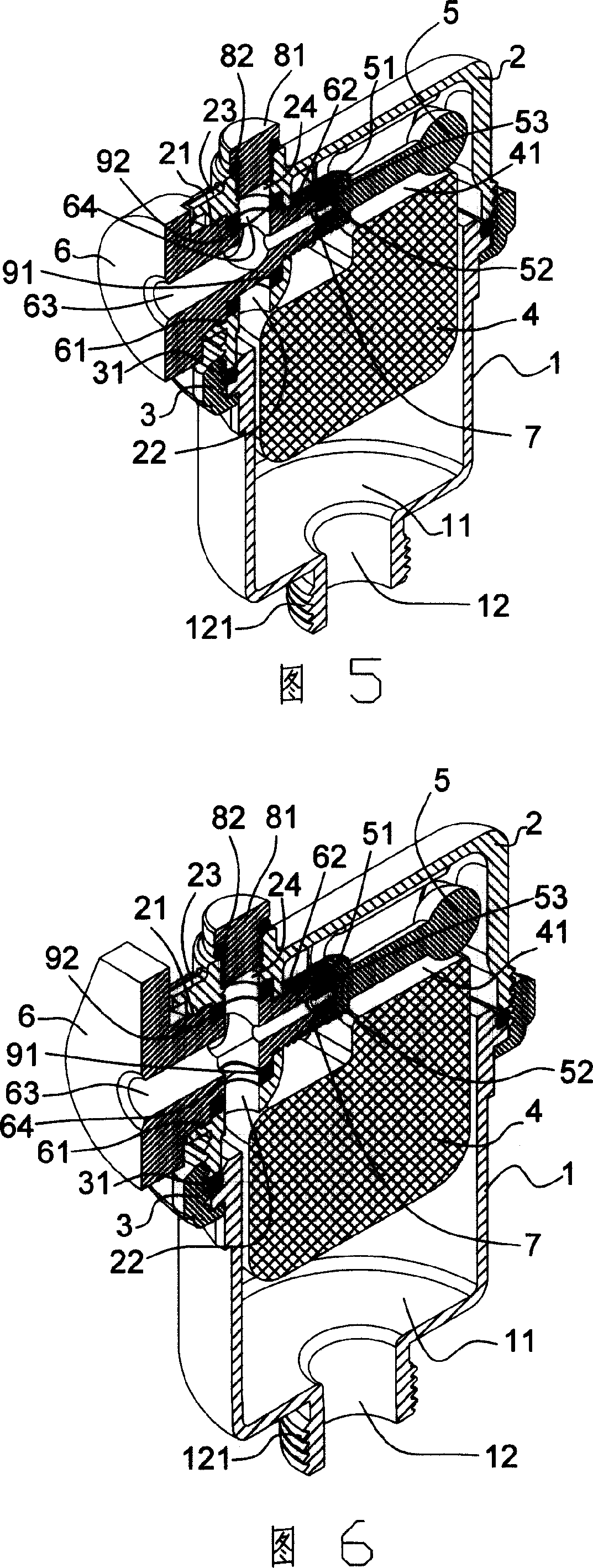
[0026] As shown in Figure 1, a new type of automatic exhaust valve includes a valve body 1 and a valve cover 2, the two are sealed and connected by a flower cap 3 to form a valve cavity 11, and an "O" is placed at the connection between the two. "Ring 31 realizes sealing, and valve body 1 lower end is provided with an air inlet 12, and the outer side of air inlet is provided with external thread or internal thread, adopts external thread 121 in the present embodiment, and it is connected with horizontal pipeline, and bonnet 2 A horizontal air outlet 21 is arranged on it.

[0027] As shown in Figure 7, a floating ball 4 is arranged inside the valve cavity 11, a slideway 41 is opened on the upper part of the floating ball 4, a connecting rod 5 is arranged inside the sliding way 41, and an engaging structure is arranged outside the end of the connecting rod. External thread 51 is adopted, a groove 52 is arranged on the end face of connecting rod 5, and a rubber washer 53 is insta...


PUM


Abstract

The invention discloses a novel automatic ventilate valve, comprising a valve body and a valve cover sealed and connected together to form a valve chamber. The bottom of the valve body is arranged with an air inlet. The valve cover is arranged with a horizontal air outlet. The valve chamber contains a floating ball whose upper part has a sliding channel with a connecting rod. The end of the connecting rod is arranged with a clamper whose end face is arranged with a groove. The groove is mounted with a pad ring. The horizontal air outlet is arranged with a handle whose head is arranged with a clamper, via one spring to engage the connecting rod. The handle is hollow to obtain a through hole whose outlet is communicated with the outer space. The inlet of the through hole is compacted with the pad ring of connecting rod. The invention can realize automatic ventilation via the air content of tube.

Description

technical field [0001] The invention relates to an exhaust valve, in particular to a novel automatic exhaust valve. Background technique [0002] The liquid medium transportation pipelines in daily life use the principle of atmospheric pressure to realize the transmission. In order to ensure the smooth flow of the pipeline, it is necessary to maintain a certain pressure difference between the inlet and outlet of the pipeline. If there is gas in the pipeline, it will have a certain impact on the pressure difference between the inlet and outlet of the pipeline, resulting in loud noise in the pipeline, failure of normal transportation of liquid media, and pipeline blockage. In actual use, the gas in the pipeline must be removed from time to time. Currently, the most commonly used method is to directly install an exhaust valve on the pipeline. Existing exhaust valves are generally divided into two types, one is an automatic structure, which can only realize a single exhaust fun...

Claims


Application Information

Patent Timeline
IPC IPC(8): F16K1/00F16K31/20
Inventor 林春晓
Owner 浙江世进水控股份有限公司
Why Eureka
Try Eureka