
Liquid crystal display

A liquid crystal display device and liquid crystal layer technology, which is applied in static indicators, nonlinear optics, instruments, etc., can solve the problems of complex manufacturing process, reduced white display transmittance, and large influence, and achieves suppressed manufacturing costs, excellent high-speed Responsive effect

Inactive Publication Date: 2007-08-08
NORTHEASTERN UNIV LIAONING +1
View PDF0 Cites 6 Cited by
  • Summary
  • Abstract
  • Description
  • Claims
  • Application Information

AI Technical Summary

Problems solved by technology

[0007] However, in the above-mentioned improved TN mode, although the viewing angle characteristics can be improved accordingly, sufficient viewing angle cannot be obtained yet.
In addition, in the electric field response in which the liquid crystal molecules are guided, the influence of backflow is large, so high-speed response cannot be achieved, and there is also the problem of sacrificing the brightness of the front side.
[0008] In addition, in the MVA mode, in order to provide protrusion-shaped structures on the substrate surface, the manufacturing process becomes complicated, which is a major cause of cost increase.
Furthermore, in order to eliminate grayscale inversion, it is necessary to reduce the transmittance of white display, so if high luminance is to be achieved, power consumption will increase
In addition, like the TN method, the impact of back flow is large, and the high-speed response is limited.

Method used


Image

  • Liquid crystal display
  • Liquid crystal display
  • Liquid crystal display

Examples


Embodiment Construction

[0034] Embodiments of the present invention will be described in detail below with reference to the accompanying drawings.

[0035] The present invention can be applied to a transmissive liquid crystal display device that uses a lighting device such as a backlight to display through light transmission, or has a transmission area and a reflection area, and uses a lighting device such as a backlight to perform display through light transmission and at the same time as an external display. A transflective liquid crystal display device that displays light by reflected light. In this embodiment mode, a case where the liquid crystal display device of the present invention is a transmissive liquid crystal display device will be described.

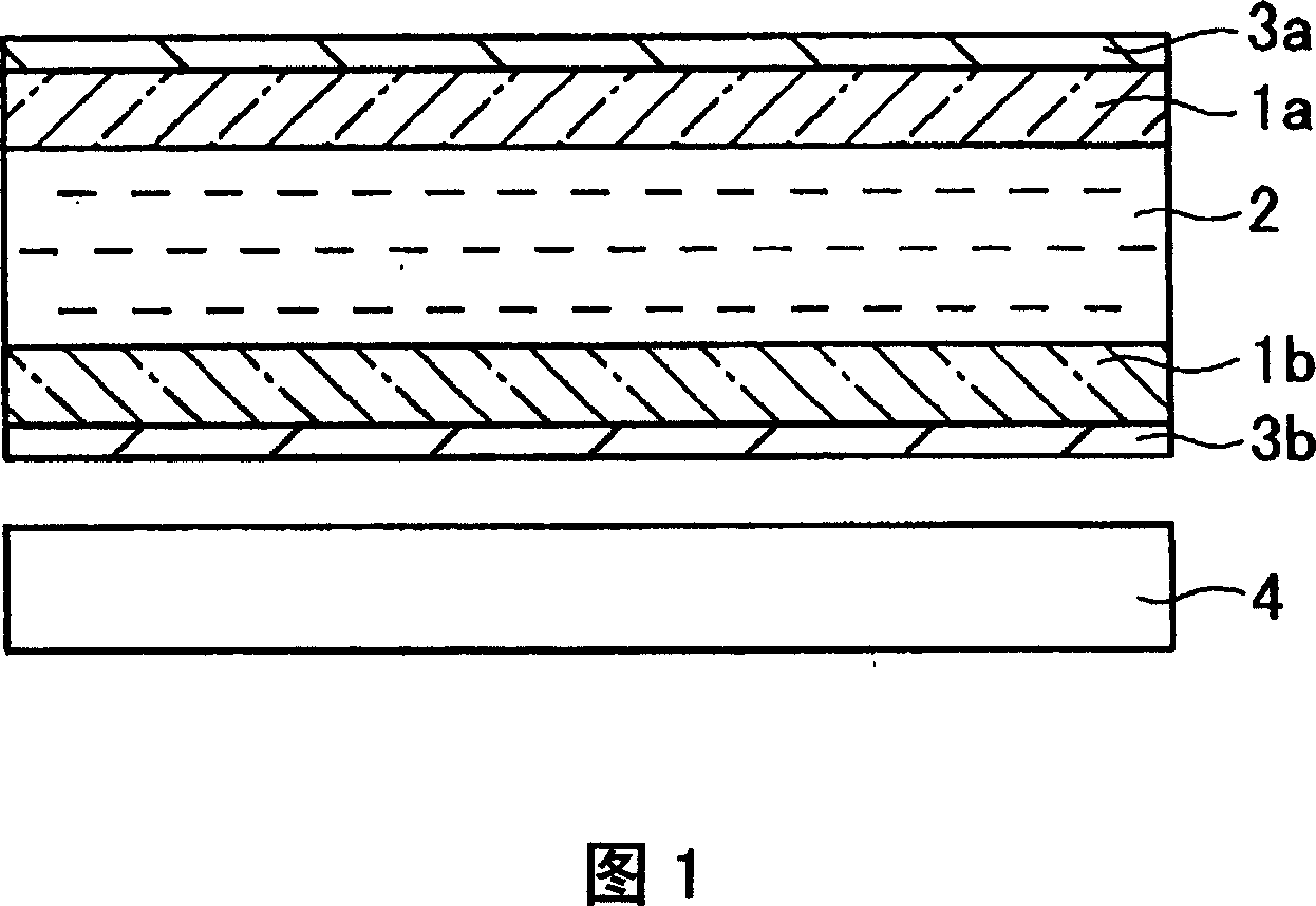
[0036] FIG. 1 is a diagram showing a schematic configuration of a liquid crystal display device according to an embodiment of the present invention. The liquid crystal display device shown in Figure 1 is mainly composed of the following parts: a ...


PUM


Abstract

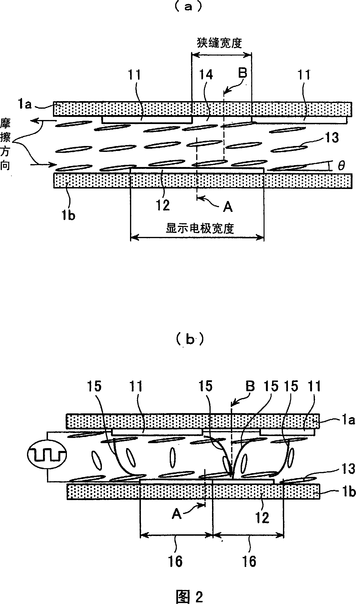
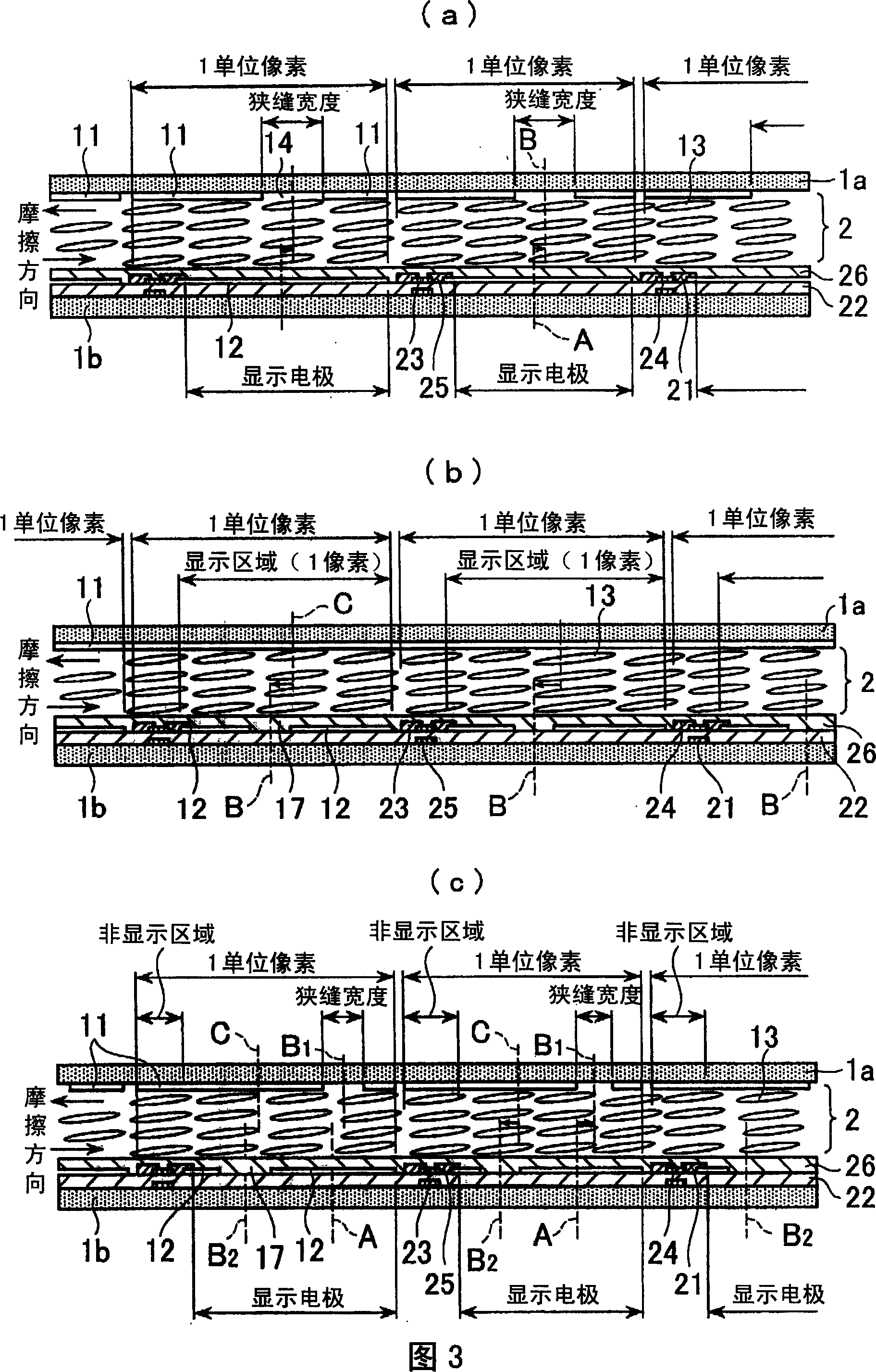
The invention discloses a liquid crystal display device, wherein, a common electrode (11) is formed in a base plate (1a) and a display electrode (12) is formed in a base plate (1b). A slit (14) is formed in the common electrode (11) at one side of the base plate (1a). The center (B) of the slit (14) is displaced from the center (B) of the display electrode facing the base plate (1b). In other words, the slit (14) canpared to the display electrode (14) looks asymmetry in the plane, so that the large perspective of the liquid crystal display device is realized, and the cost can be kept down. The invention is suitable for moving and has excellent high speed response.

Description

technical field [0001] The present invention relates to a liquid crystal display device capable of wide viewing angle, high-speed response, and bright display. Background technique [0002] In recent years, liquid crystal displays (LCDs (Liquid Crystal Displays)) have been widely used in display units of personal computers, car navigation systems, digital cameras, digital video cameras, mobile phones, liquid crystal televisions, portable information terminals, and the like. However, LCDs have a narrower field of view than conventional CRTs (Cathode-RayTube), requiring improvements in viewing angle characteristics. [0003] As a means of widening the viewing angle, for example, it is disclosed that an opening pattern (slit) is formed in a display region of a pair of facing electrodes of a TN type liquid crystal display device (Patent Document 1). The slits are formed such that their longitudinal directions are perpendicular to the initial (when no voltage is applied) alignme...

Claims


Application Information

Patent Timeline
Patent Type & Authority Applications(China)
IPC IPC(8): G02F1/1333G02F1/133
Inventor 内田龙男石锅隆宏鹿野满大泉满夫林祐三
Owner NORTHEASTERN UNIV LIAONING
Learn More