
Method for controlling application program

A technology of application programs and touch panels, applied in the input/output process of data processing, instruments, electrical digital data processing, etc., can solve problems such as multi-time

Active Publication Date: 2007-08-15
ASUSTEK COMPUTER INC
View PDF0 Cites 3 Cited by
  • Summary
  • Abstract
  • Description
  • Claims
  • Application Information

AI Technical Summary

Problems solved by technology

Thus, the user has to go through multiple steps and spend a lot of time when controlling the application

Method used


Image

  • Method for controlling application program
  • Method for controlling application program
  • Method for controlling application program

Examples


Embodiment Construction

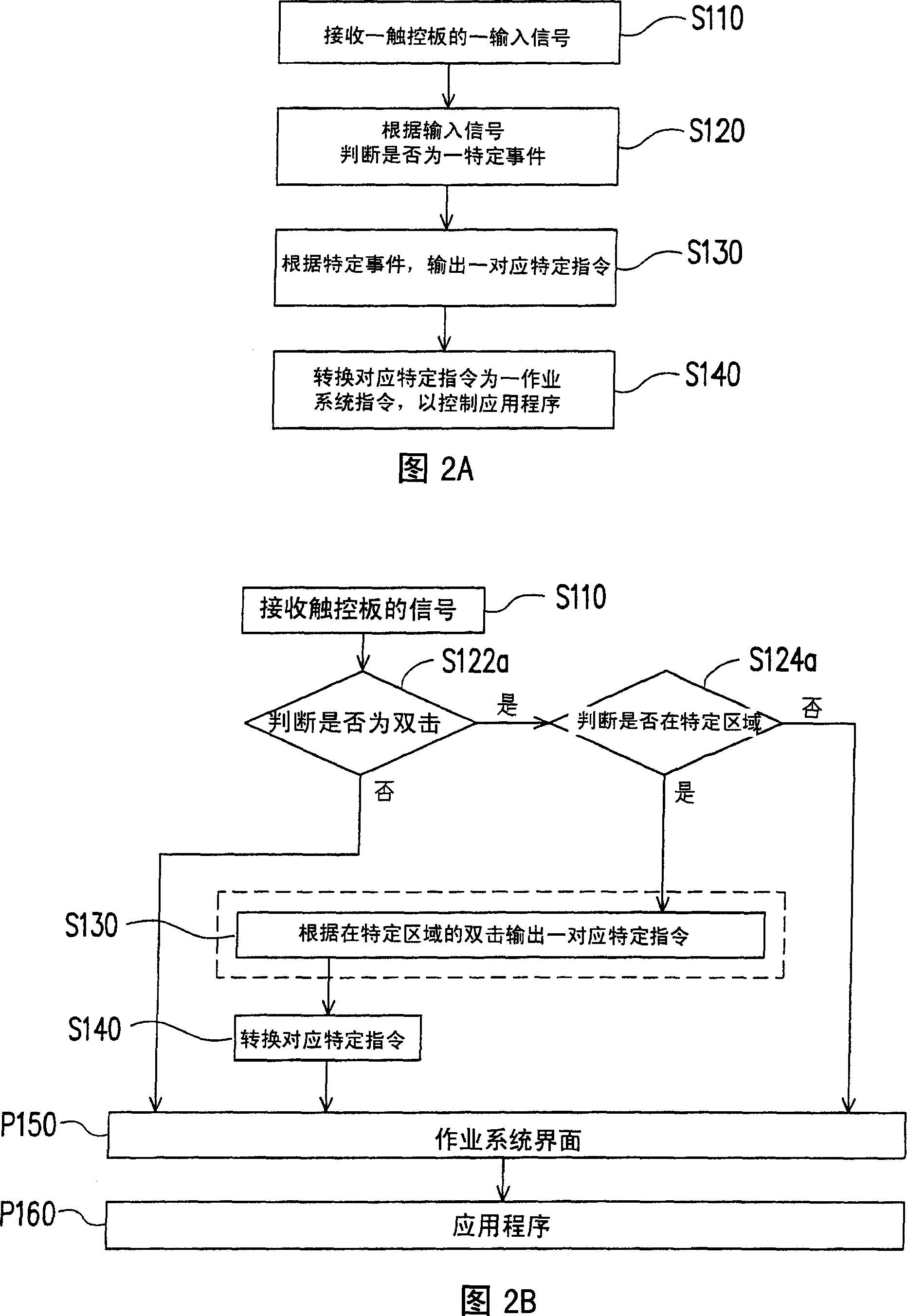
[0042] FIG. 2A is a flowchart of a method for controlling an application program according to an embodiment of the present invention. Please refer to FIG. 2A first, the method for controlling an application program in this embodiment includes the following steps. First, step S110 is performed, that is, an input signal of a touch panel is first received. Next, proceed to step S120, after receiving the input signal, and then judge whether it is a specific event according to the input signal. Afterwards, proceed to step S130, and output a corresponding specific instruction according to the specific event. Then, proceed to step S140, converting the corresponding specific command into an operating system command to control the application program. In more detail, due to different input signals, the detailed flow of the method for controlling the application program will be slightly changed, which will be described in detail below.

[0043] FIG. 2B and FIG. 2C respectively illust...


PUM


Abstract

This invention relate to one method to control application program, which comprises the following steps: firstly receiving one trigger control board input signal; then according to input signal judging whether it is one special affair; then according to the affair outputting one special order; then converting the special order as one operation system order to control application program. This invention provides one method to control application program to fulfill orders.

Description

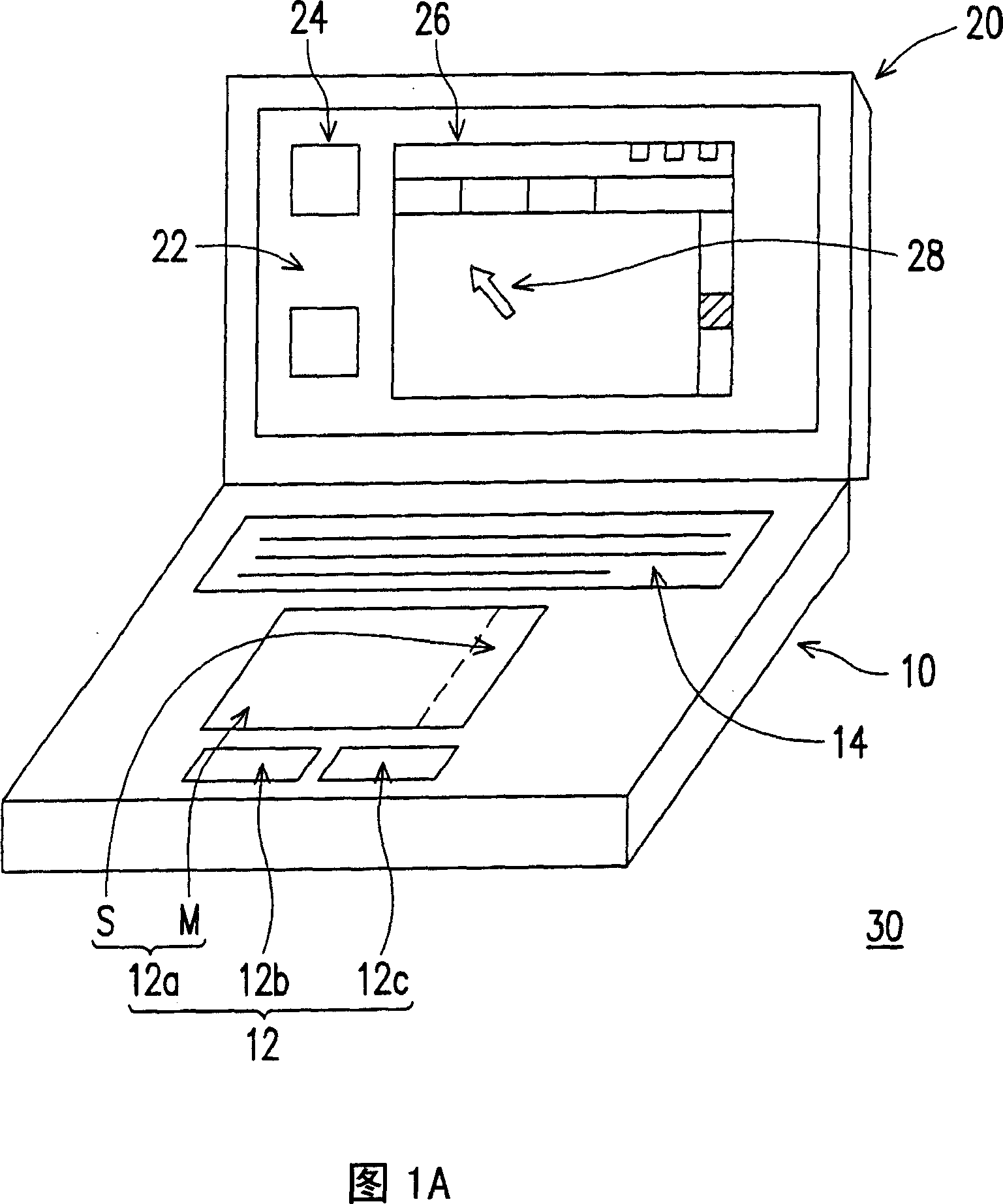
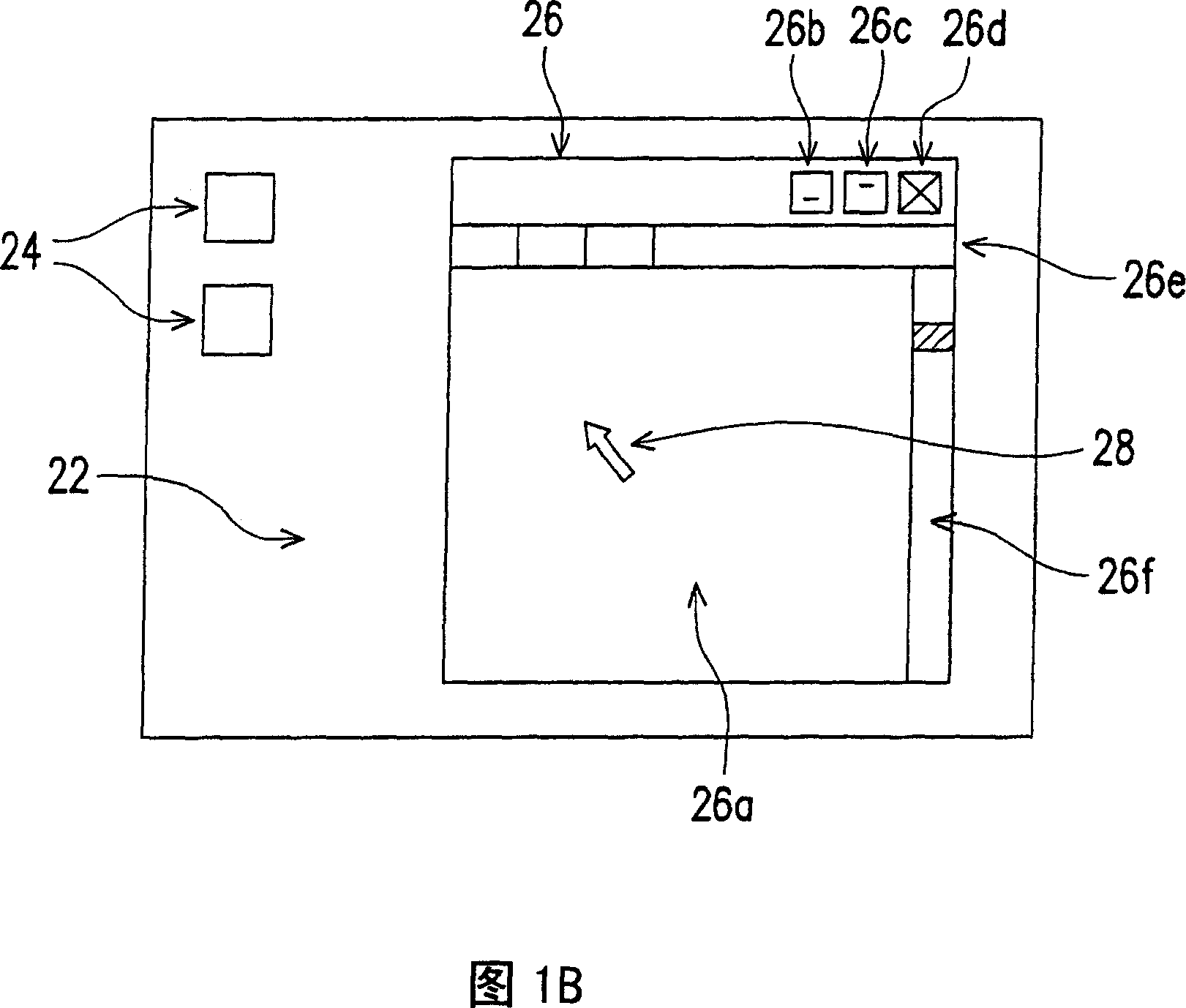
technical field [0001] The present invention relates to a method for controlling an application program, in particular to a method for controlling an application program by using a touch pad (touch pad) input signal. Background technique [0002] Since a notebook computer (notebook) integrates a display screen, a host computer, and an input device into one body, the design of the notebook computer itself has many considerations different from that of a desktop computer. As far as the function of controlling the position of the cursor on the screen is concerned, for the convenience of carrying, the notebook computer abandons the design of the traditional mouse (mouse), and instead uses the touchpad technology and buttons integrated on the case to realize To achieve the function of the mouse. This technology has also been the most common technology used by notebook computers to replace the mouse. [0003] FIG. 1A is a schematic diagram of a conventional notebook computer, an...

Claims


Application Information

Patent Timeline
Patent Type & Authority Applications(China)
IPC IPC(8): G06F3/041G06F3/0488
Inventor 林伟博戴孝桦
Owner ASUSTEK COMPUTER INC
Learn More