
Method for operating an injection molding machine

A technique for injection molding machines, machine tools, applied in the field of operating injection molding machines

Active Publication Date: 2007-08-15
KRAUSSMAFFEI TECH GMBH
View PDF0 Cites 2 Cited by
  • Summary
  • Abstract
  • Description
  • Claims
  • Application Information

AI Technical Summary

Problems solved by technology

this is not compliant

Method used


Image

  • Method for operating an injection molding machine
  • Method for operating an injection molding machine
  • Method for operating an injection molding machine

Examples


Embodiment Construction

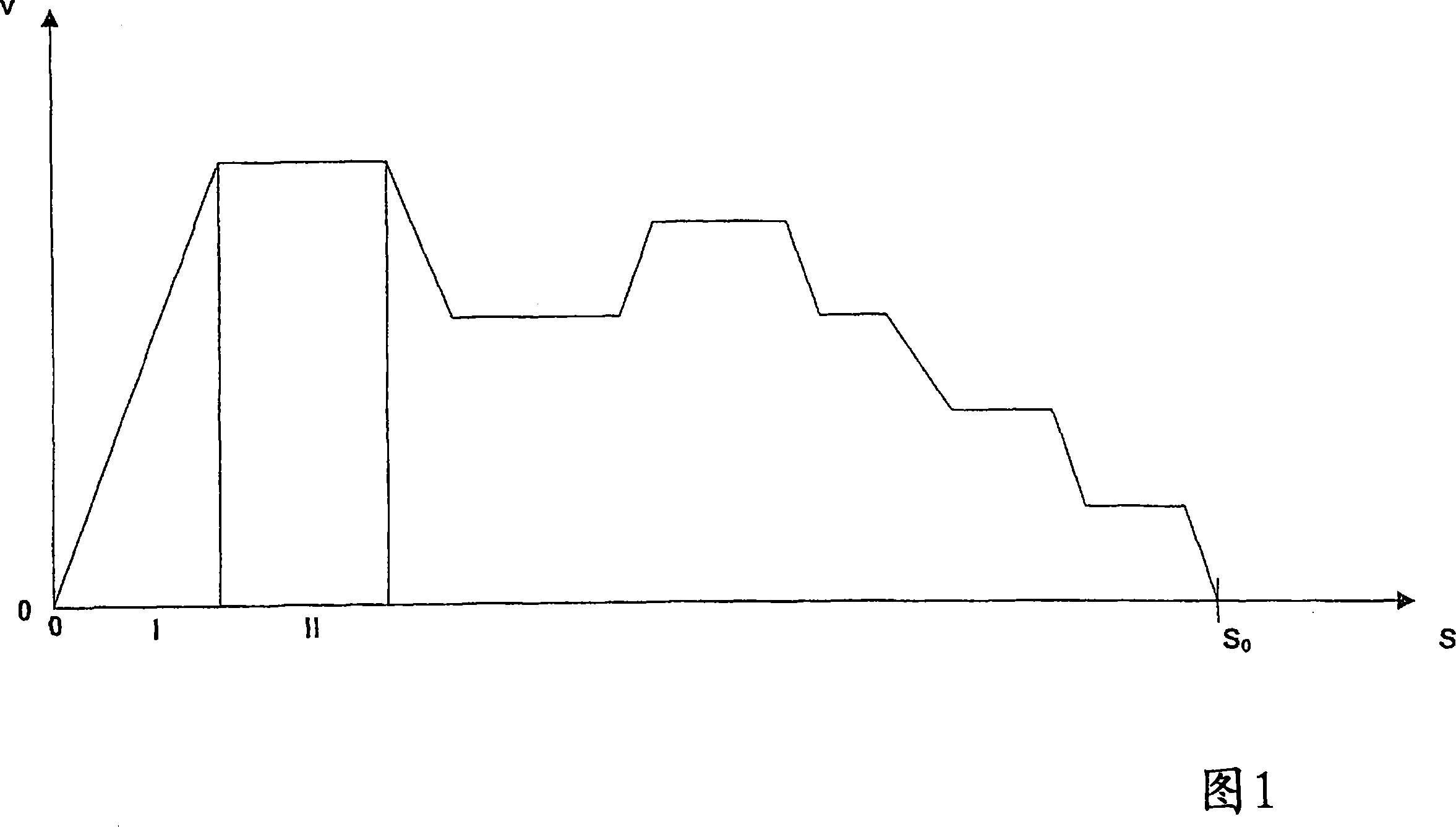
[0020] FIG. 1 shows a preliminary distribution of initial variables, on the basis of which the method according to the invention is used to automatically determine a target variable distribution for the mold protection of the mold of the injection molding machine. Figure 1 shows a moving mold half along its closing or moving distance from 0 to S 0 speed distribution. In region I the predetermined speed increases and thus the starting variable V increases to the starting speed. In zone II the mold half moves constantly at the starting speed. In other regions, the predetermined profile of the starting variable V extends in a stepwise distribution with deceleration and acceleration phases and with a constant speed phase. At the end of the travel distance, the travel speed of the mold becomes zero of course when the mold is closed. Such velocity profiles move at different velocities V along distances from 0 to S 0 Changes in are easily predictable or predictable, since the max...


PUM


Abstract

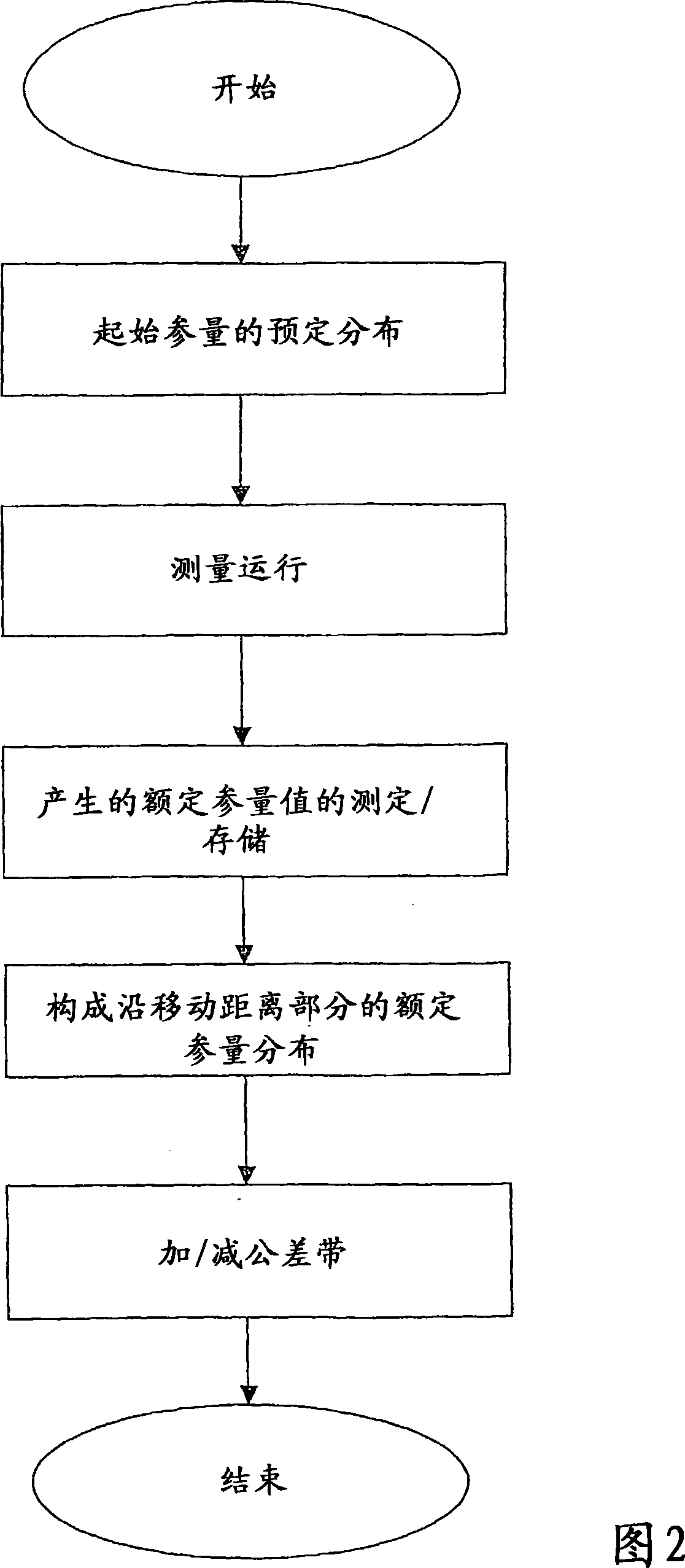
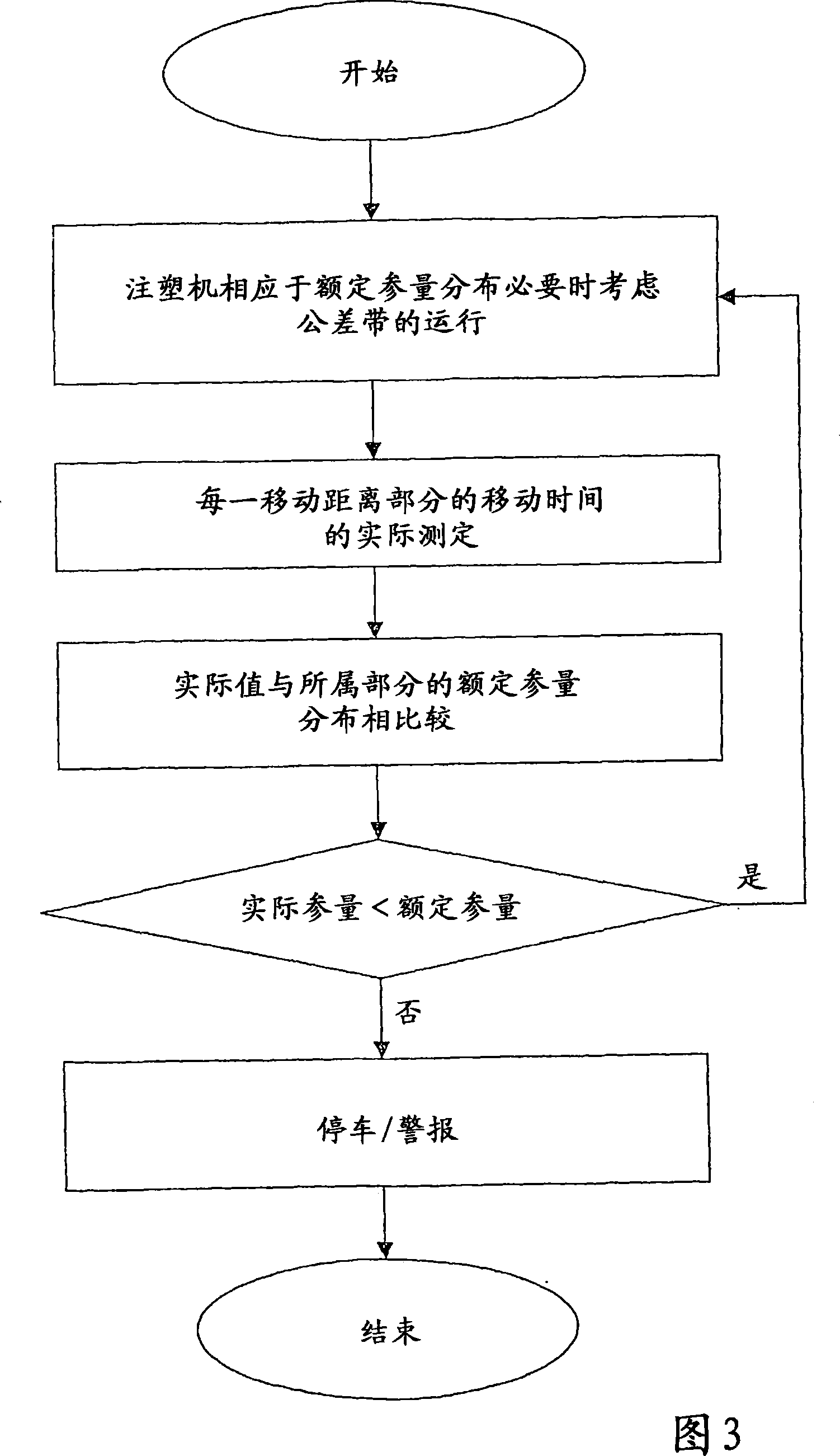
The invention relates to a method for operating an injection molding machine, particularly a method for securing tools of an injection molding machine. According to said method, a setpoint variable curve is determined along at least one section of a displacement path of a molding tool in a setpoint variable determination phase, and the injection molding machine is operated according to the determined setpoint variable curve in a subsequent operational phase. A preset curve of at least one initial variable is predefined, the molding tool is driven in accordance with the preset curve of the initial variable in a test run, at least one resulting value of the setpoint variable is measured and stored during the test run, and a setpoint variable curve is formed along the section of the displacement path from the measured values of the setpoint variable.

Description

technical field [0001] The invention relates to a method for operating an injection molding machine, wherein a setpoint variable distribution for mold protection of the injection molding machine is determined and the injection molding machine is operated according to the determined setpoint variable distribution. Background technique [0002] In a known method for establishing a nominal force profile for the closing force of a mold, such as the mold of an injection molding machine, in a nominal force determination phase, at the end of the closing process of a mold of the injection molding machine a Stage or multistage pressure distribution. When determining this pressure distribution, the process is carried out manually and empirically, that is, the operator of the injection molding machine reduces the driving force of a moving mold half incrementally along the end region of a mold closing phase until the driving force is ideally still only Frictional resistance in the bear...

Claims


Application Information

Patent Timeline
Patent Type & Authority Applications(China)
IPC IPC(8): B29C45/76
CPCB29C45/766B29C45/76B29C45/7653B29C45/84B29C2945/76006B29C2945/76013B29C2945/76066B29C2945/76468B29C2945/76505B29C2945/76702B29C2945/76943B29C2945/76976
Inventor G·格林
Owner KRAUSSMAFFEI TECH GMBH
Learn More