Method and device for automatically producing a stator of an electric machine

A stator and equipment technology, applied in the manufacture of motor generators, electrical components, electromechanical devices, etc., can solve the problems of high technology and cost, and achieve the effect of stabilizing the structure

Inactive Publication Date: 2020-07-17
MIBA AUTOMATION SYST GES
View PDF9 Cites 0 Cited by
  • Summary
  • Abstract
  • Description
  • Claims
  • Application Information

AI Technical Summary

Problems solved by technology

This manufacturing method can only be automated conditionally, or only with relatively high technical expenditure and only with tight tolerances for the U-shaped curved conductor elements.

Method used


Image

  • Method and device for automatically producing a stator of an electric machine
  • Method and device for automatically producing a stator of an electric machine
  • Method and device for automatically producing a stator of an electric machine

Examples


Embodiment Construction

[0035] First of all, it is established that in the different described embodiments, the same parts are provided with the same reference numerals or the same component designations, wherein the disclosure contained in the entire description can be translated into meanings with the same The same reference numerals or the same components refer to the same parts. Equally, the position specifications selected in the description, such as upper, lower, side, etc., refer to the directly described and shown figures and these position specifications can be logically translated to the new position when the position is changed .

[0036] The term "in particular" is understood below to mean that it can here be a possible more specific configuration or a more detailed description of an object or a method step, but not necessarily a mandatory preferred embodiment or a compulsory embodiment of an object or a method step. process way.

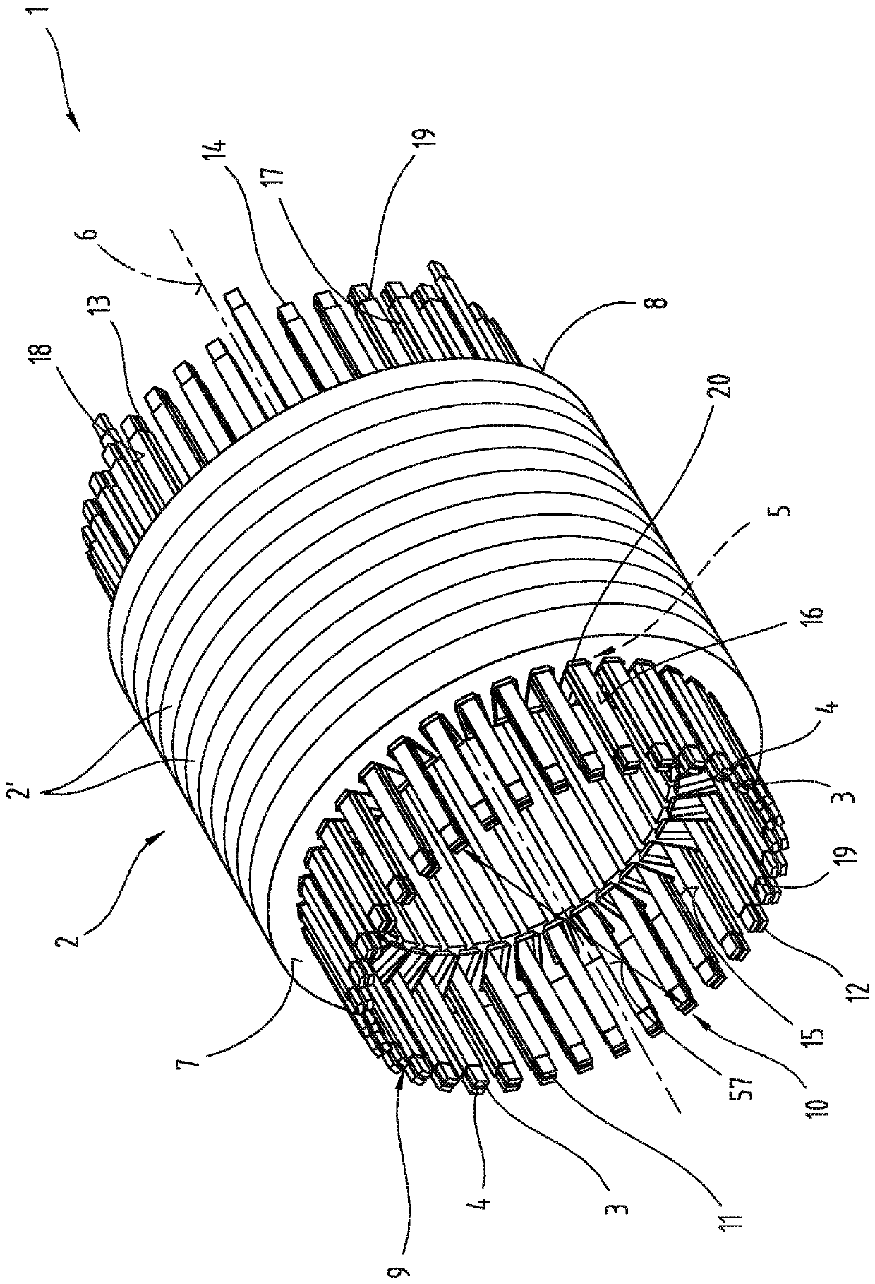
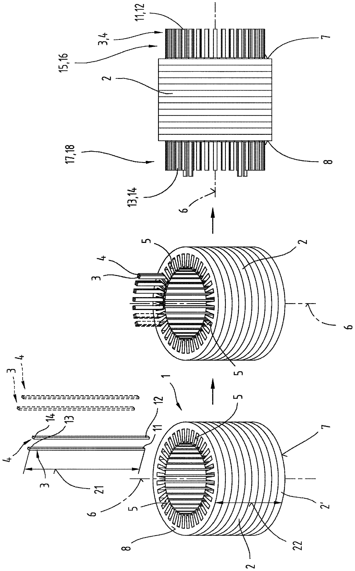
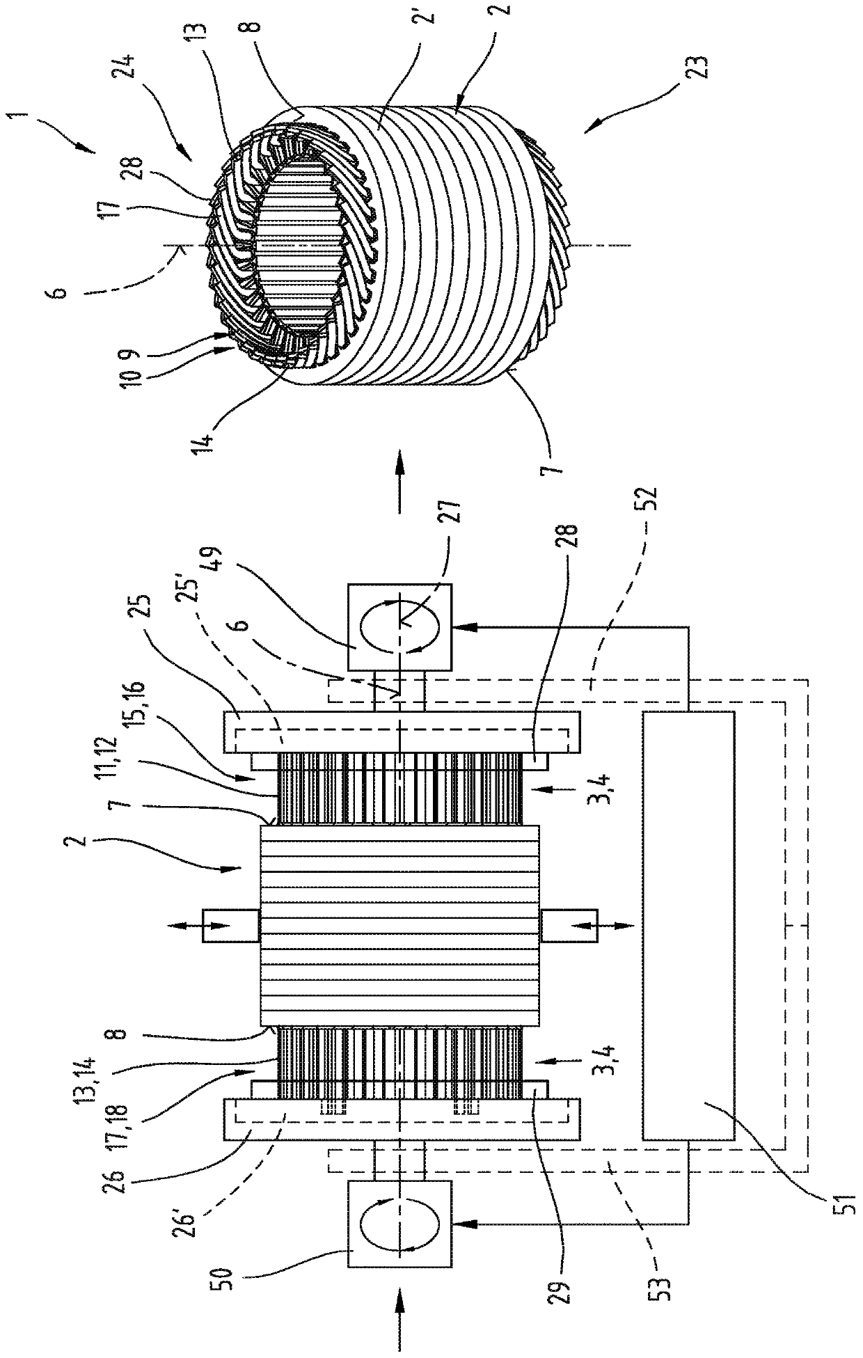
[0037] exist figure 1 A possible embodiment for forming ...


PUM


Abstract

The invention relates to a method and a device for automatically producing a semi-finished stator (1) of an electric machine. A substantially hollow cylindrical laminated core (2) is provided with a plurality of stacked sheet-metal laminates (2') which define a main axis (6). At least one of the longitudinal ends (11, 12; 13, 14) of rod-shaped conductor elements (3, 4) for producing an electric winding protrude relative to the first and/or second end faces (7, 8) of the laminated core (2) such that the conductor elements form lines (15, 16; 17, 18) that protrude from the laminated core (2) atat least one of the end faces (7, 8) of the laminated core (2). The protruding lines (15, 16; 17, 18) of the conductor elements (3, 4) are bent in the direction of the circular circumferential direction of the hollow cylindrical laminated core (2) by means of at least one bending tool (25, 25'; 26, 26') mounted so as to be rotatable about a rotational axis (27). Additionally, the longitudinal ends(11, 12, 13, 14) of the conductor elements (3, 4) are brought into a specified radial target position with respect to the laminated core (2) by means of calibrating forces which act radially in the direction of the rotational axis (27) and which are exerted by at least one calibrating device (28, 29) with calibrating fingers (30, 31) that can be adjusted in a controlled manner and are oriented radially towards the rotational axis (27) of the at least one bending tool (25, 25', 26, 26').

Description

technical field [0001] The invention relates to a method and a device for the automated production of semi-finished stators of electric motors, as described in claims 1 and 8 . Background technique [0002] From JP2003259613A a method for producing an electrical winding for a stator of an electric machine is known. In this case, a plurality of substantially U-shaped conductor elements are inserted into receiving grooves of the hollow cylindrical stator lamination stack. The projection of the leg end of the U-shaped bent conductor element protruding onto one of the two end faces of the stator lamination stack is then bent in the circumferential direction of the stator lamination stack by means of a concentrically arranged disk-shaped bending tool, wherein , in the radial direction of the stator lamination stack, the directly adjoining projections of the conductor elements are bent in oppositely arranged circumferential directions, so that cross-running conductor projections ...

Claims


Application Information

Patent Timeline
Patent Type & Authority Applications(China)
IPC IPC(8): H02K15/00
CPCH02K15/0087H02K15/085H02K15/09
Inventor A·福克纳M-M·普里莫拉克D·谢瑞
Owner MIBA AUTOMATION SYST GES
Why Eureka
Try Eureka