Bonding device and bonding method for display panel

A technology for display panels and bonding devices, which is applied in the directions of optics, instruments, electrical components, etc., can solve problems such as panel suspension, panel damage, and Y-direction deviation of bonding, and achieve the effects of simplifying bonding actions, improving takt time, and reducing mechanisms

Inactive Publication Date: 2019-04-12
WUHAN CHINA STAR OPTOELECTRONICS SEMICON DISPLAY TECH CO LTD
View PDF6 Cites 0 Cited by
  • Summary
  • Abstract
  • Description
  • Claims
  • Application Information

AI Technical Summary

Problems solved by technology

[0003] 1. Integrated circuit (IC) bonding: the height of the support table is too low or too high (at the level of 100 μm), causing the panel to be suspended or tilted, and the panel may be damaged when the pressure head is pressed down
[0004] 2. Chip on film (COF), flexible printed circuit (FPC) or other flexible materials are bonded. Due to the need for flexibility, the current materials are getting thinner and more prone to bending. If the support table The height is low, and the bending of FPC and COF is serious (some more than 1cm), which may interfere with the bearing seat, resulting in missing joint of FPC and COF. If the support table is too high, the Y-direction offset of the joint may occur

Method used


Image

  • Bonding device and bonding method for display panel
  • Bonding device and bonding method for display panel
  • Bonding device and bonding method for display panel

Examples


Embodiment Construction

[0022] In order to make the above and other objectives, features, and advantages of the present disclosure more comprehensible, preferred embodiments of the present disclosure will be exemplified below in detail with reference to the attached drawings. Furthermore, the direction terms mentioned in this disclosure, such as up, down, top, bottom, front, back, left, right, inside, outside, side layer, surrounding, center, horizontal, transverse, vertical, longitudinal, axial , radial direction, the uppermost layer or the lowermost layer, etc., are only directions for referring to the attached drawings. Therefore, the directional terms used are used to explain and understand the present disclosure, but not to limit the present disclosure.

[0023] In the figures, structurally similar units are denoted by the same reference numerals.

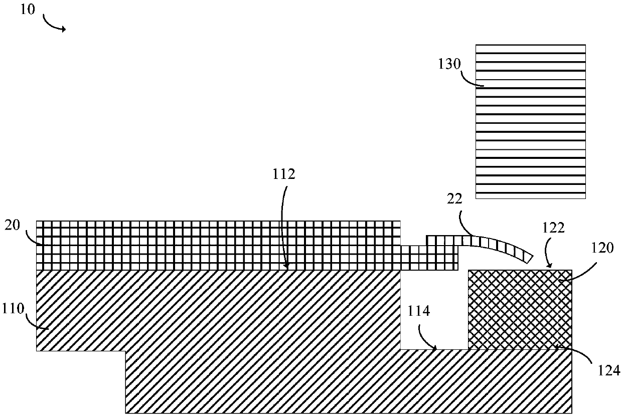
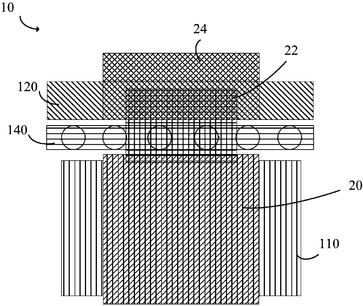
[0024] Figure 1-2 A schematic structural view of a bonding device for a display panel according to an embodiment of the disclosure is shown.

[...


PUM


Abstract

The invention provides a bonding device and a bonding method for a display panel. The bonding device for the display panel comprises a supporting table and a bearing base; the bearing base is integrally arranged on the supporting table; and the first surface of the supporting table and the first surface of the bearing base are used for bearing the display panel and are located on the same horizontal plane. According to the bonding device, the supporting table and the mechanism of the bearing base are integrally designed structurally, so that the bonding action of the bonding device is simplified, the beat time is improved, and the corresponding mechanisms and / or cost can be reduced.

Description

【Technical field】 [0001] The disclosure relates to the field of display technology, and in particular, to a bonding device for a display panel and a bonding method for a display panel. 【Background technique】 [0002] Bonding is an important process in the current module process of organic light-emitting display devices and liquid crystal displays. In the current jointing device used for display panels, the support platform and the bearing seat are independent mechanisms, and the current joining process, the operation process is as follows: the panel is placed on the support platform by the mechanical arm, and then the support platform moves to the joint area (carrying seat directly above), and then descend to the bearing seat, and the pressure head descends to press the panel. Because the height and position of the support table may change with the operation or switching models, there are the following risks during the operation: [0003] 1. Integrated circuit (Integrated ...

Claims


Application Information

Patent Timeline
Patent Type & Authority Applications(China)
IPC IPC(8): H01L51/56G02F1/13
CPCG02F1/1303H10K71/00
Inventor 张定伟
Owner WUHAN CHINA STAR OPTOELECTRONICS SEMICON DISPLAY TECH CO LTD
Why Eureka
Try Eureka