Multiple coaxal cable and its making method

A technology for multi-core cables and cables, which is applied in the manufacture of cables/conductors, end components of multi-core cables, cables, etc., and can solve problems such as disconnection of cable groups

Inactive Publication Date: 2007-08-29
SUMITOMO ELECTRIC IND LTD
View PDF1 Cites 9 Cited by
  • Summary
  • Abstract
  • Description
  • Claims
  • Application Information

AI Technical Summary

Problems solved by technology

[0009] In such a conventional connector mount type multi-coaxial cable, even if the respective lengths of the cables are adjusted according to the background art such as JP-A-2005-235690, it is likely that the cable groups 3a arranged near the respective sides , Open circuit occurs at 3c

Method used


Image

  • Multiple coaxal cable and its making method
  • Multiple coaxal cable and its making method
  • Multiple coaxal cable and its making method

Examples


Embodiment Construction

[0023] Hereinafter, specific embodiments of the present invention are explained with reference to the accompanying drawings, and the following exemplary embodiments do not limit the scope of the present invention.

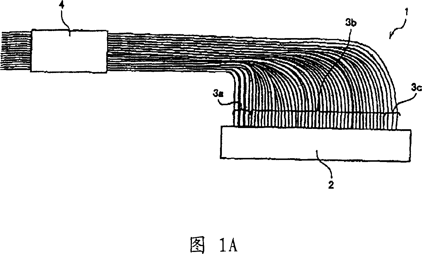
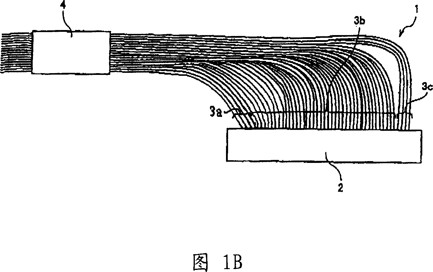
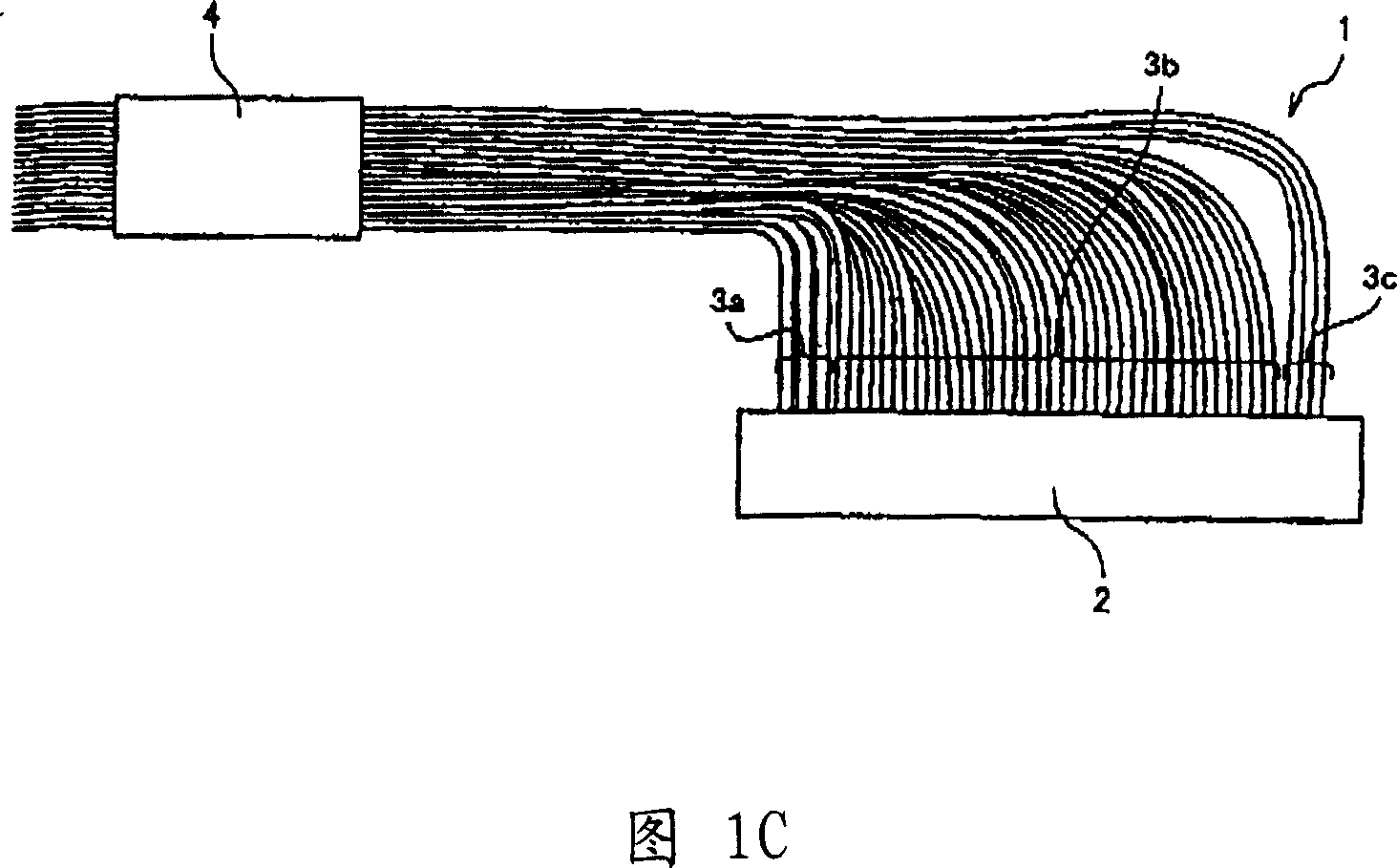
[0024] 1A to 1C are views illustrating a connector-mounted multi-coaxial cable according to an embodiment of the present invention. 2A to 2C are views showing the overall structure of the connector-mounted multi-coaxial cable shown in any one of FIGS. 1A to 1C .

[0025] A connector-mounted multi-coaxial cable 1 according to an embodiment of the present invention is a cable in which respective ends of a plurality of cables are arranged at predetermined intervals so as to be formed into a flat shape, and an electrical connector (connector) 2 Connect to each end of the cable. The cables may include coaxial cables or ultra-thin insulated cables. The middle portion of the cable of the multi-coaxial cable 1 is bundled by a band-shaped band 4 .

[0026] As shown in FI...


PUM


Abstract

A multi-coaxial cable comprising: a plurality of cables arranged at predetermined intervals so as to form a flat shape at respective ends thereof; and an electrical connector connected to each of the plurality of cables end connections. The middle portions of the plurality of cables are bundled. At least one end, the plurality of cables are bent, and at least one of the plurality of cables is formed to have a length under which the cable can be bent so as to be perpendicular to the The longitudinal direction of the electrical connector.

Description

technical field [0001] The invention relates to a multi-coaxial cable, which has a plurality of insulated cables or coaxial cables, and a manufacturing method thereof. More particularly, the present invention relates to a multi-coaxial cable, wherein the middle portion of the cable is bundled, and the plurality of cables are arranged in a flat shape and connected with electrical connectors at their respective ends, and its manufacturing method. Background technique [0002] In recent years, laptop computers, mobile phones, and miniature cameras have been widely used, whereby reduction in size and weight, and improvement in speed and image quality are required for such information communication devices. To cope with this demand, extremely thin insulated cables or coaxial cables are used to connect the device body and the liquid crystal display, as well as for wiring within the device. Furthermore, due to the convenience of wiring, a harness-type wiring member is adopted, in...

Claims


Application Information

Patent Timeline
Patent Type & Authority Applications(China)
IPC IPC(8): H01B7/00H01B7/08H01B13/00H01R11/11
Inventor 仙波弘之
Owner SUMITOMO ELECTRIC IND LTD
Why Eureka
Try Eureka