Current blocking element and ozone generation device

A current cutting and generating device technology, which is applied to electrical components, corona discharge devices, ozone preparation, etc., can solve the problem of fuse connection plate falling, and achieve the effect of suppressing conductor disconnection

Active Publication Date: 2020-01-10
MITSUBISHI ELECTRIC CORP
View PDF13 Cites 0 Cited by
  • Summary
  • Abstract
  • Description
  • Claims
  • Application Information

AI Technical Summary

Problems solved by technology

If there is a short circuit and a large current flows, the four fuse conductors 36 will melt and the three fuse connecting plates 35 will fall off.

Method used


Image

  • Current blocking element and ozone generation device
  • Current blocking element and ozone generation device
  • Current blocking element and ozone generation device

Examples


Embodiment Construction

[0033] Embodiment 1﹒

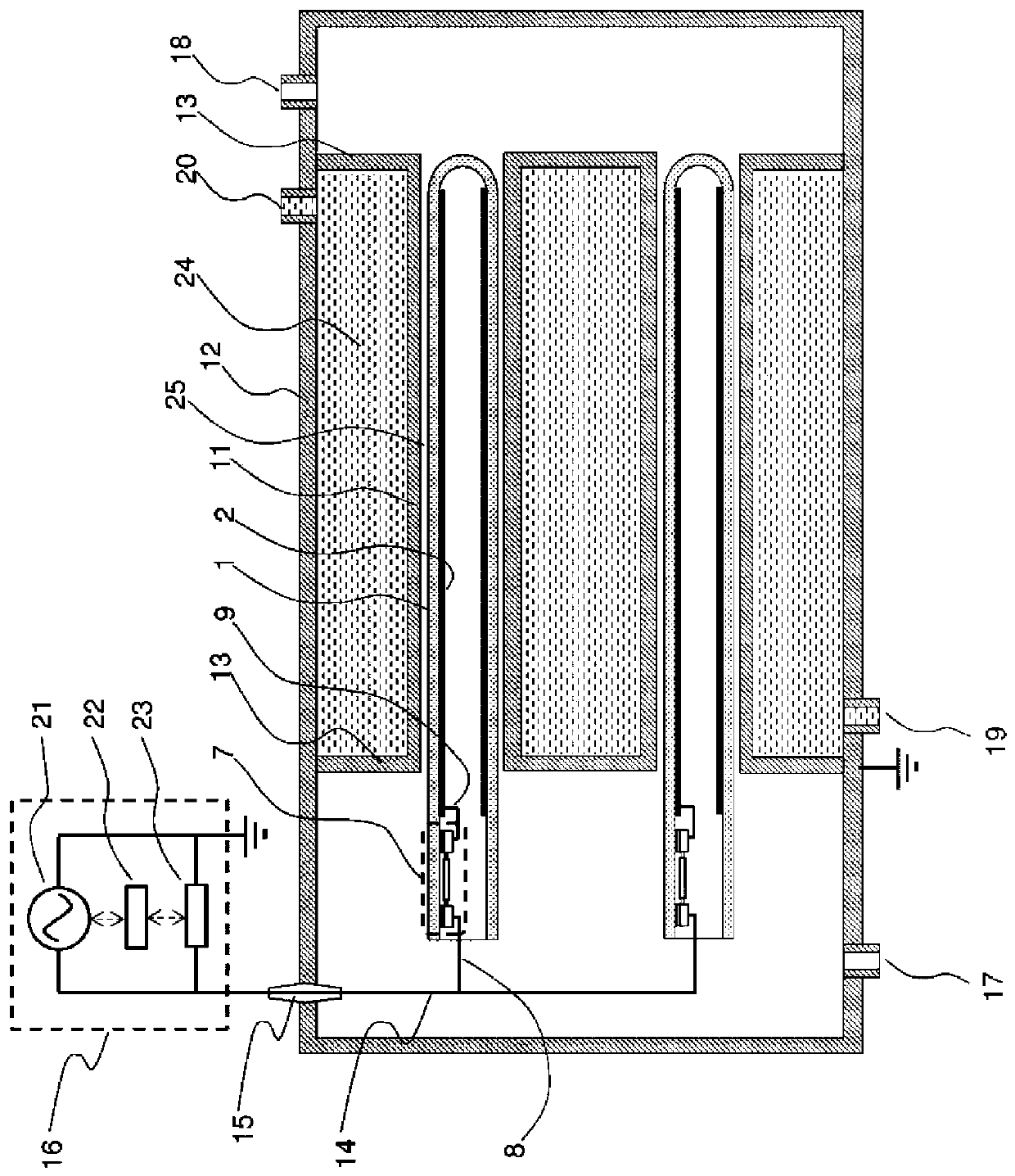
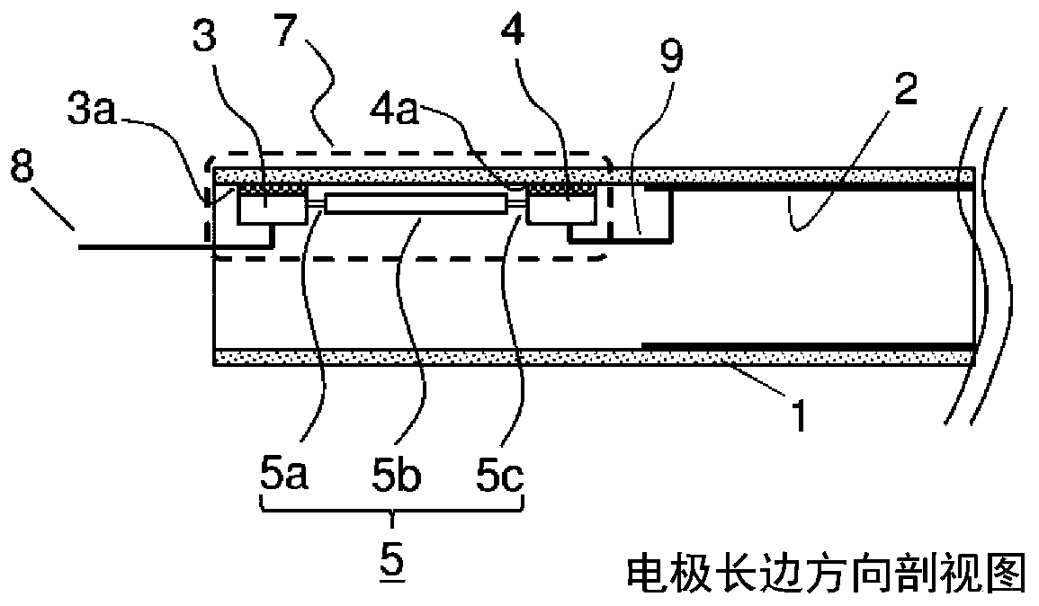
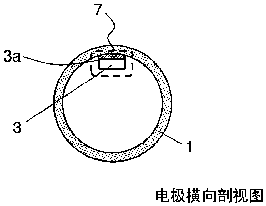
[0034] figure 1 It is a cross-sectional view showing a schematic configuration of an ozone generator according to Embodiment 1 of the present invention. figure 1 Among them, inside the ozone generator main body container 12, a cylindrical dielectric tube 1 and a ground metal electrode 11 are paired to form a single discharge tube. figure 1In order to describe the discharge tubes in detail, only two discharge tubes are shown, but in a large-capacity ozone generator, several hundreds of discharge tubes are provided inside one ozone generator main body container 12 . For example, the dielectric tube 1 is formed of a cylindrical glass tube, and the ground metal electrode 11 is formed of a pipe made of stainless steel. A narrow discharge gap 25 is formed between it and the ground metal electrode 11 . One end (right end) of the dielectric tube 1 is closed, and the other end (left end) is opened. A voltage applying electrode 2 is provided inside the diel...


PUM

PropertyMeasurementUnit
lengthaaaaaaaaaa
widthaaaaaaaaaa
lengthaaaaaaaaaa

Abstract

An ozone generation device provided with a plurality of discharge tubes, each having a discharge gap between a voltage application electrode and a ground metal electrode with a dielectric disposed therebetween, wherein an oxygen-containing gas flows in each discharge gap, and an alternating-current voltage from an alternating-current power supply is applied across the voltage application electrodes and the ground metal electrodes in order to cause the oxygen-containing gas to be discharged to become ozonized gas. Midway along the path of the electrical feed from the alternating-current power supply to the voltage application electrodes of the plurality of discharge tubes, there is connected a current blocking element comprising: a fusing element in which fuse conductors that melt due to the flow of an over-current are disposed on both sides of an intermediate conductor; and plate-shaped fixed electrodes connected to both sides of the fusing element, each of the fixed electrodes havinga plate surface fixed to a surface of a base of the dielectric by means of a fixing material.

Description

technical field [0001] The present invention relates to an ozone generator that ozonates an oxygen-containing gas by electric discharge, and particularly relates to a current cutoff element provided for operation protection. Background technique [0002] In a large-capacity ozone generator, more than 100 discharge tubes are used as loads connected to a power source. In such an ozone generator, according to the variation of the discharge tubes, a device is proposed in which each discharge tube is provided with a fuse so that even if a short-circuit discharge occurs in one discharge tube, an arc discharge is generated from the discharge tube. In the case of , only the discharge tube can be disconnected from the power supply, and the operation of the entire device can be continued (for example, refer to Patent Document 1). [0003] During the operation of the device, the insulation of the dielectric tube constituting a certain discharge tube is damaged, resulting in the openin...

Claims


Application Information

Patent Timeline
Patent Type & Authority Applications(China)
IPC IPC(8): H01H85/05C01B13/11H01H23/00
CPCC01B13/11H01H23/00H01H85/05H01H85/0017H01H85/48H01H85/20H01H85/0026H01T19/00H05H1/2406
Inventor 中谷元永山贵久高内大辅尾台佳明
Owner MITSUBISHI ELECTRIC CORP
Why Eureka
Try Eureka