Ventilator and building

A ventilation device, air technology, applied in the direction of climate sustainability, air handling details, ventilation systems, etc.

Inactive Publication Date: 2007-09-05
MAX CO LTD
View PDF1 Cites 5 Cited by
  • Summary
  • Abstract
  • Description
  • Claims
  • Application Information

AI Technical Summary

Problems solved by technology

When an air conditioner equipped with an indirect evaporative cooling device is installed in a house, temperature control is important, but there is a problem that the temperature control required for use in a house cannot be performed with the existing device.

Method used


Image

  • Ventilator and building
  • Ventilator and building
  • Ventilator and building

Examples


Embodiment Construction

[0065] 0020

[0066] Hereinafter, embodiments of the ventilator and building of the present invention will be described with reference to the drawings.

[0067] 0021

[0068]

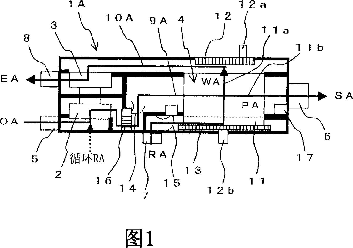
[0069] FIG. 1 is a configuration diagram showing an example of a ventilator 1A according to the first embodiment. A ventilator 1A of the first embodiment includes an air supply fan 2 , an exhaust fan 3 , and an indirect evaporation cooling unit 4 .

[0070] 0022

[0071] Also, the ventilator 1A includes an outside air inlet 5 for sucking in outside air OA (OutsideAir) from the outside, and a supply air outlet 6 for blowing supply air SA (SupplyAir) into the room. Further, the ventilator 1A includes a return air inlet 7 for sucking in return air RA (ReturnAir) from the room, and an exhaust outlet 8 for blowing out exhaust air EA (ExhaustAir) to the outside. In addition, each blower port and each suction port are connected to indoors and outdoors, for example, through ducts etc. which are not shown ...


PUM


Abstract

The purposes of the present invention is a ventilator having an indirect vaporizing and cooling function and a 24-hour ventilation function and installable in a housing. The ventilator (1D) stops supplying a working air (WA) to an indirect vaporizing and cooling unit (4) in heating operation. An outside air (OA) sucked from an outside air suction port (5) is heat-exchanged with a return air (RA) sucked from a return air suction port (7) by a heat exchange unit (31). In winter season, the temperature of the outside air (OA) is increased since the temperature of the return air (RA) is higher than that of the outside air (OA), and the indirect vaporizing and cooling unit (4) stops supplying the working air (WA), a product air (PA) passing a product air flow passage (11b) is not cooled. Thus, the outside air (OA) heated by the heat exchange unit (31) is supplied as a supply air (SA) from a supply air outlet port (6).

Description

technical field [0001] 0001 [0002] The present invention relates to a ventilating device installed in a house to ventilate the outdoors and indoors and a building equipped with the ventilating device, in particular to a ventilating device and an indirect vaporization cooling function for cooling air by utilizing the heat of vaporization of water. building. Background technique [0003] 0002 [0004] An air conditioner for cooling a building has been proposed previously, and an air conditioner equipped with an indirect evaporative cooling device that cools air using heat of vaporization of water has been proposed (for example, see JP-A-2004-190970). The indirect evaporative cooling device is a structure in which sensible heat (temperature) is exchanged between flow paths separated by a partition wall. The heat of vaporization of water is used to cool the air in one flow path, and cold energy is exchanged between the flow path and the other flow path. It cools the air pas...

Claims


Application Information

Patent Timeline
Patent Type & Authority Applications(China)
IPC IPC(8): F24F3/147F24F7/08F24F1/0059
CPCF24F2001/0092Y02B30/545F24F5/0035F24F1/0007Y02B30/54F24F1/0059F24F11/30F24F2203/1032
Inventor 石田敏也针谷工内田晃悦小池三仁
Owner MAX CO LTD
Why Eureka
Try Eureka