
Straight-through current transformer with anti-theft electric surface shield

A current transformer, anti-theft technology, applied in the direction of inductors, instruments, circuits, etc., can solve the problem of no anti-theft design, and achieve the effect of simple structure, easy installation and broad application prospects

Inactive Publication Date: 2007-09-12
HUBEI SHENGJIA ELECTRIC EQUIP
View PDF0 Cites 10 Cited by
  • Summary
  • Abstract
  • Description
  • Claims
  • Application Information

AI Technical Summary

Problems solved by technology

[0004] In order to solve the problem that the current feed-through current transformer with built-in voltage extraction has no anti-stealing design, the present invention provides a feed-through current transformer with an anti-stealing mask

Method used


Image

  • Straight-through current transformer with anti-theft electric surface shield
  • Straight-through current transformer with anti-theft electric surface shield
  • Straight-through current transformer with anti-theft electric surface shield

Examples


specific Embodiment approach 1

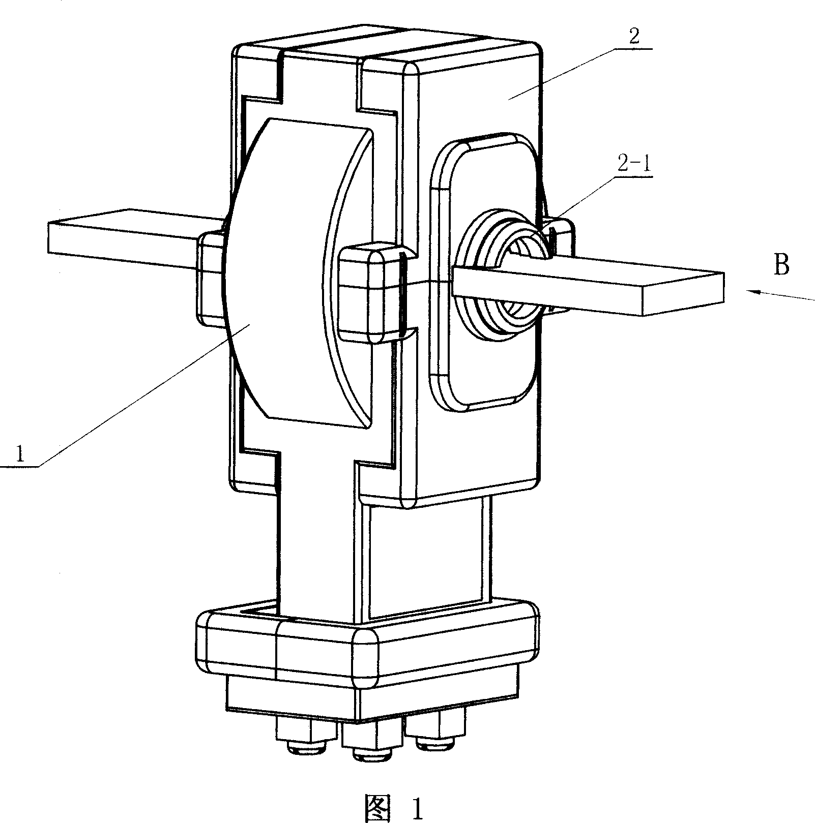
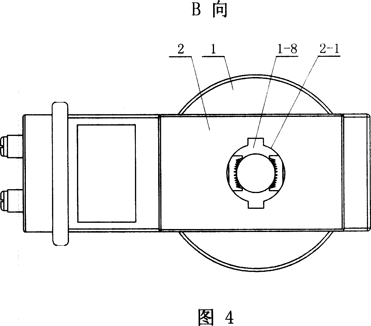
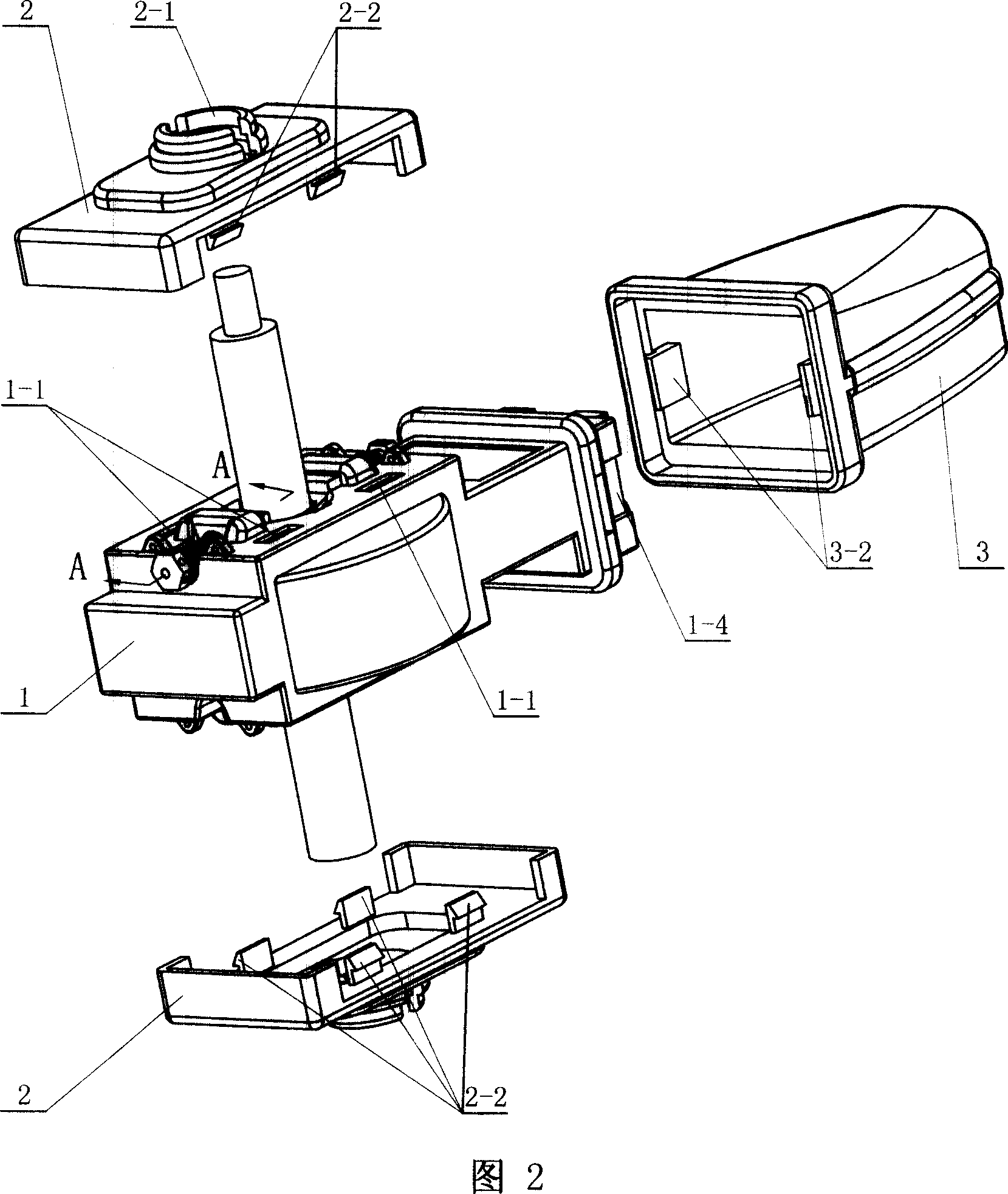
[0012] Specific embodiment one: (referring to Fig. 1, Fig. 2, Fig. 4, Fig. 5, Fig. 6) present embodiment consists of transformer body 1 and anti-theft electricity mask 2 fixed on the surface of transformer body 1, the anti-theft The middle part of the electric mask 2 is provided with a threading hole 2-1 for a primary line; the anti-stealing mask 2 is connected with the surface of the transformer body 1 in a non-detachable manner; as shown in Figure 2, the anti-stealing mask 2 is provided with Clipping piece 2-2, the transformer body 1 is provided with a clipping interface 1-1 that is compatible with the clipping piece 2-2, and the anti-theft mask 2 is provided with a clipping piece 2-2 for insertion The card interface 1-1 on the transformer body 1 realizes card connection.

[0013] In addition, the clamping member 2 - 2 and the card interface 1 - 1 in this embodiment are not limited to two on one side as shown in FIG. 2 , and can also be set in any number according to actual ...

specific Embodiment approach 2

[0016] Specific embodiment two: (referring to Fig. 7) the difference between this embodiment and specific embodiment one is that described anti-theft mask 2 comprises No. 1 cover body 21 and No. 2 cover body 22, and No. 1 cover body 21 is provided with Clamping piece 21-1, the second cover body 22 is provided with a card interface 22-1 adapted to the clamping piece 21-1; the clamping piece 21-1 on the first cover body 21 is inserted into the second The card connection is realized in the card interface 22-1 on the cover body.

[0017] The clamping parts 21-1 on the No. 1 cover body 21 in this embodiment can be two, and they are respectively arranged on both sides of the No. 1 cover body 21, as shown in FIG. 7; of course, the clamping parts 21-1 The number and positions of the number and positions can also be set at other positions on the No. 1 cover body 21 according to actual needs. In addition, it may also be the case that the No. 2 cover body 22 is provided with a snap-in p...

specific Embodiment approach 3

[0025]Specific embodiment three: (see Fig. 1, Fig. 2, Fig. 4, Fig. 5, Fig. 6, Fig. 7, Fig. 11, Fig. 12, Fig. 13) The difference between this embodiment and specific embodiment one or two is that The secondary terminal of the transformer body 1 is fixedly provided with a secondary terminal anti-stealing cover body 3, and the other end of the secondary terminal anti-stealing cover body 3 has a wiring hole 3-1, as shown in the figure 2, specifically, the secondary terminal anti-theft cover body 3 is provided with a clip 3-2, and the transformer body 1 is provided with a clip matching the clip 3-2. Interface 1-4, the clamping piece 3-2 on the anti-theft cover body 3 of the secondary terminal is inserted into the clamping interface 1-4 on the transformer body 1 to realize the clamping connection.

[0026] Preferably, as shown in Figure 7, the secondary terminal anti-theft cover body 3 includes a No. 1 cover body 31 and a No. 2 cover body 32, and the No. The No. 1 cover body 32 is ...


PUM


Abstract

This invention relates to a straight-through current transformer with thief proof electricity veil. The invention includes transformer noumenon (1) and thief proof electricity veil (2). Middle of thief proof electricity veil (2) set up threading hole (2- 1); Thief proof electricity veil (2) dead join with end face of transformer noumenon (1) threading hole. This invention is able to effectively prevent electric larceny behavioral occurring by decreasing pressure of watt hour meter. from technically it deter pressure decreasing of watt-hour meter, thereby avoid problem of electric quantity understatement. The invention possesses merit of structure simplicity, cost low and fail safe.

Description

technical field [0001] The invention relates to the field of electric power transformers, in particular to a through-hole type anti-theft current transformer. Background technique [0002] At present, current transformers and watt-hour meters are usually used in conjunction with electric energy metering. The amount measured by an electric energy meter is mainly determined by the product of the three elements of voltage, current, power factor and time. Therefore, changing any one of the three elements can make the energy meter rotate slowly, stop or even reverse, so as to achieve the purpose of stealing electricity. In the prior art, the feed-through current transformer with built-in voltage extraction has no design to prevent artificial power theft, which is not conducive to the management of the power management department. [0003] For the existing core-through current transformer with built-in voltage extraction, there are many ways to achieve the purpose of artificial s...

Claims


Application Information

Patent Timeline
IPC IPC(8): G01R11/24G01R11/04
CPCG01R15/183H01F38/24
Inventor 万家盛
Owner HUBEI SHENGJIA ELECTRIC EQUIP
Learn More