Display unit

A display unit and non-display technology, applied in electrical components, static indicators, optics, etc., can solve problems such as halo phenomenon, weakening light energy, and affecting the display effect and quality of liquid crystal panel 1

Inactive Publication Date: 2007-09-12
WINTEK CORP
View PDF0 Cites 11 Cited by
  • Summary
  • Abstract
  • Description
  • Claims
  • Application Information

AI Technical Summary

Problems solved by technology

[0005] However, within the effective emission range of the light source 3, when the light encounters the transparent adhesive material, the light will change its path inside the adhesive material because the adhesive material itself has light-guiding properties. This situation will not only weaken the energy of the light , and the halo phenomenon occurs on the glue material,

Method used


Image

  • Display unit
  • Display unit
  • Display unit

Examples


Embodiment Construction

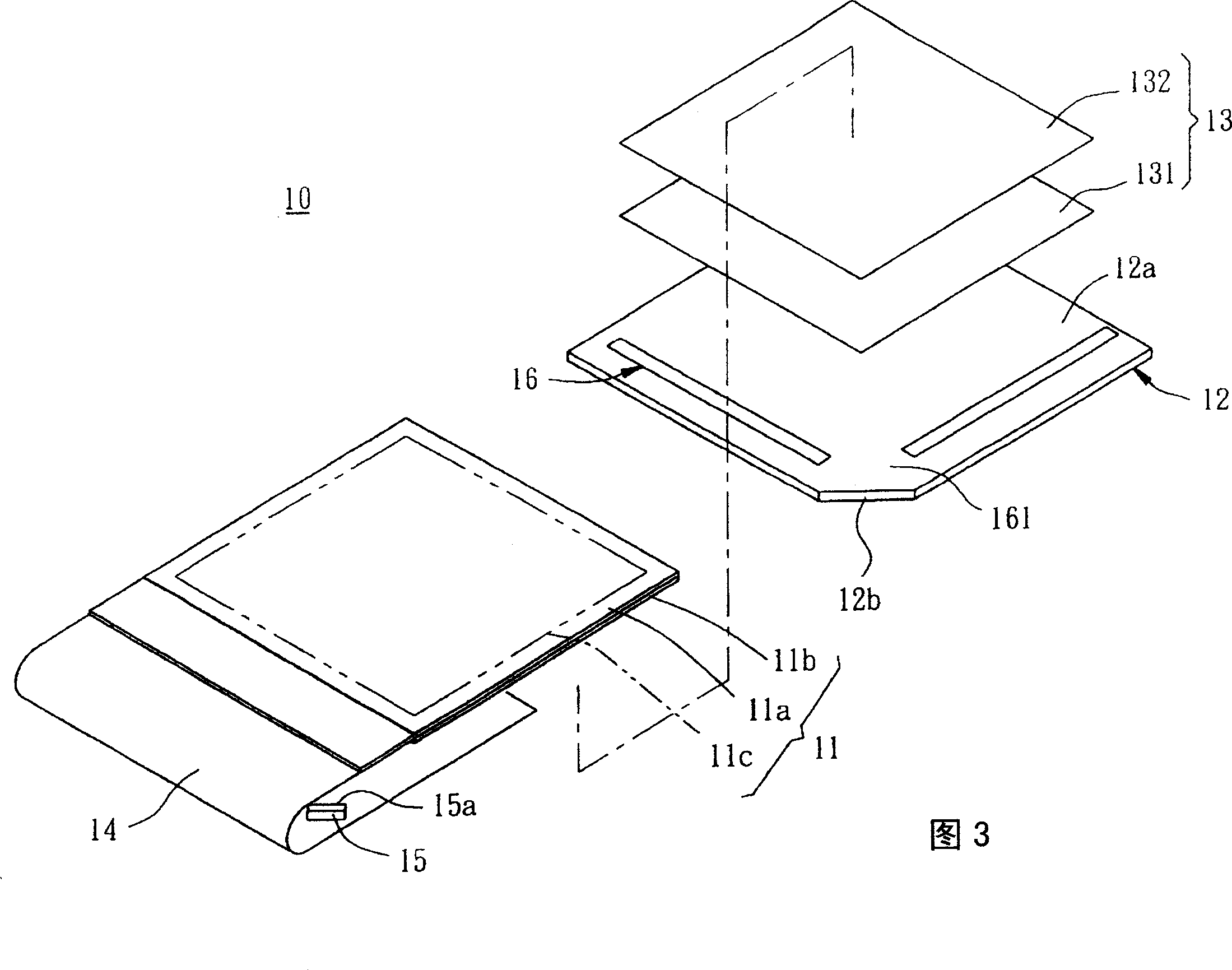
[0028] Please refer to Fig. 3 to Fig. 5, which is a display unit of a preferred embodiment of the present invention, the aforementioned display unit is a liquid crystal display 10, which includes a liquid crystal panel 11, a light guide plate 12, an optical film group 13, A circuit board (such as the flexible printed circuit board 14 on the surface), a light source for the LED 15 and a double-sided adhesive tape 16, wherein:

[0029] The liquid crystal panel 11 comprises an upper glass substrate 11a and a lower glass substrate 11b. The two glass substrates 11a, 11b are sealed and filled with liquid crystal material. The liquid crystal panel 11 forms a display surface 11c and a non-display surface (not labeled in the figure). ), the display surface 11c can display text or graphics.

[0030] The light guide plate 12 is disposed below the non-display surface of the liquid crystal panel 11. The light guide plate 12 has a light emitting surface 12a and at least one light incident s...


PUM


Abstract

The invention is a display unit, comprising a liquid crystal panel, a circuit board, a light guide plate, at least a light source and a double-faced adhesive tape, where the light source is connected with the circuit board and located outside the light guide plate, and the double-faced adhesive tape is used to bond the liquid crystal panel with the light guide plate and has at least a gap which corresponds to the light source to reduce the irradiation of the light source on the double-faced adhesive tape and there is a halo formed at the gap.

Description

technical field [0001] The present invention relates to liquid crystal displays, and more particularly to a display unit with reduced halation that exists near a light source. Background technique [0002] By the way, the display effect and quality of LCD panels are important considerations for consumers when purchasing this product. For this reason, the industry has invested a lot of money and technology research and development, hoping to effectively improve the display effect and quality of LCD panels. [0003] However, some displays often find their hidden defects after the assembly is completed. If the aforementioned defects exist in the backlight module, the halo phenomenon caused by the light generated by the light source passing through the double-sided tape is now shown in Figure 1. The structure of the display shown in 2 illustrates the halo phenomenon that exists in this structure: [0004] The display structure includes a liquid crystal panel 1, a flexible print...

Claims


Application Information

Patent Timeline
IPC IPC(8): G02F1/133G02F1/1335H05K1/00
Inventor 潘玺文许志铭王星发林明传
Owner WINTEK CORP
Why Eureka
Try Eureka