Pipe joint

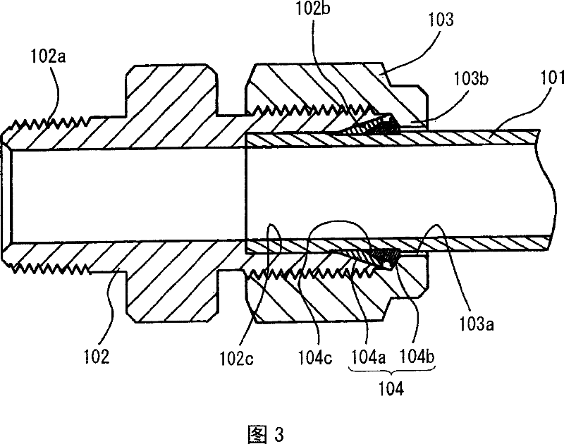
A technology for pipe joints and pipe walls, applied in the field of pipe joints, can solve problems such as difficulty in maintaining pipe holding conditions and sealing conditions, and weakening conditions of sleeve 104 biting pipe 101, etc., to achieve the effects of reducing manufacturing costs and improving efficiency and productivity

Inactive Publication Date: 2007-09-19
DENSO CORP +1
2 Cites 3 Cited by

AI-Extracted Technical Summary

Problems solved by technology

In this configuration, however, if the tube 101 is pulled or jerked, the condition for the sleeve 104 to bite into the tube 101 will be we...

Method used

[0049] In addition, the radially inner edge 18a of the end portion 18 of the lock ring 4 bites or drills into the first and second tubes 1, thereby partially constricting the outer peripheral portions of the first and second tubes 1. In this way, the radially inner edge 18a of the end portion 18 of the locking ring 4 is in close contact with the first an...

Abstract

A pipe joint has a joint main body, a union nut connected to the joint main body, and a lock ring. The lock ring has a tubular wall, and a first axial end and a second axial end of the tubular wall are deformable by inner walls of tapered hole portion of the joint main body and the union nut. The lock ring has a first tapered opening portion providing a first groove for receiving a first end of a first pipe member and a second tapered opening portion providing a second groove for receiving a second end of a second pipe member, in a radial inside of the tubular wall. A radial outer surface of the first tapered opening portion and a radial outer surface of the second tapered opening portion are tapered such that the first groove and the second groove are narrowed toward its ends, respectively.

Application Domain

Joints with sealing surfaces

Technology Topic

EngineeringMechanical engineering

Image

  • Pipe joint
  • Pipe joint
  • Pipe joint

Examples

  • Experimental program(1)

Example Embodiment

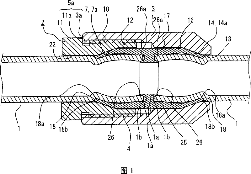
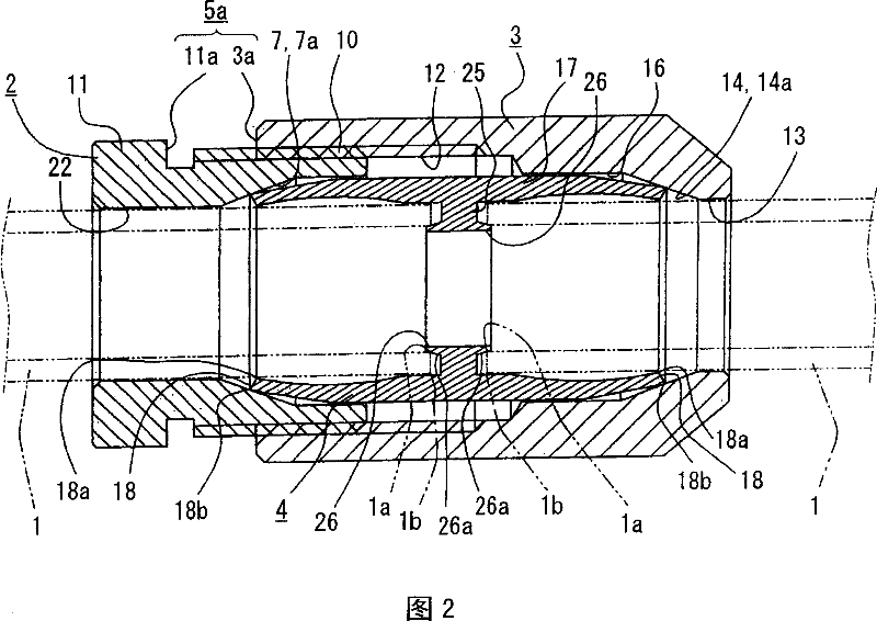
[0025] Hereinafter, an embodiment of the present invention will be described with reference to FIGS. 1 and 2 . As shown in FIG. 1 , the pipe joint is used to connect the straight ends of two pipes 1 at the same time. Hereinafter, the right tube 1 in FIGS. 1 and 2 is called the first tube 1 , and the left tube in FIGS. 1 and 2 is called the second tube 1 .
[0026] The pipe joint usually has a joint body 2, a union nut 3 screwed on the joint body 2, and a lock ring 4 on the inner circumference of the joint body 2 and the union nut 3, and the lock ring 4 is connected to the first tube 1a is joined to the second pipe 1b. In addition, the pipe joint has a tightening distance restricting portion 5 a for restricting the tightening distance or tightening amount of the union nut 3 relative to the joint main body 2 .
[0027] The joint main body 2 is made of, for example, a metal having a predetermined hardness, such as carbon steel, stainless steel, or copper alloy. The joint main body 2 has a substantially pipe shape. The joint main body 2 has on its first end (left end in FIG. 1 ) a first opening 22 as an insertion hole for inserting the first pipe 1, and has a second Open your mouth.
[0028] In addition, the joint body 2 has a tapered bore portion 7 defining an axial tapered bore between the first opening 22 and the second opening. Specifically, in the tapered hole portion 7, the diameter of the tapered hole gradually increases from the first opening 22 toward the second opening. The diameter of the second opening of the joint body 2 is equal to the maximum diameter of the tapered hole of the tapered portion 7 .
[0029] The joint body 2 has a male threaded portion 10 on the outer periphery of the second end to engage with the union nut 3 . The joint main body 2 also has a flange portion 1 on the outer periphery of its first end. The flange portion 1 has, for example, a hexagonal shape when viewed in the axial direction so as to be held by a jig such as a wrench.
[0030] The union nut 3 is made of a material having a hardness equal to that of the joint main body 2 . The union nut 3 may be made of the same material as the joint body 2 . For example, the union nut 3 has a substantially tubular shape defining a through hole therein. A radially inner wall of the first end of the union nut 3 is formed with a threaded portion. Accordingly, the first end of the union nut 3 provides a threaded bore portion 12 to engage with the male threaded portion 10 of the fitting body 2 . That is, the union nut 3 is configured such that the first end of the union nut 3 is screwed onto and engaged with the outer periphery of the second end of the joint main body 2 .
[0031] On its second end, the union nut 3 has an insertion opening 13 for insertion of the second tube 1 . In addition, the union nut 3 has a tapered hole portion 14 defining a tapered hole that communicates with the insertion opening 13 . In the tapered hole portion 14 , the diameter of the tapered hole gradually increases in the tightening direction, ie toward the first end of the union nut 3 .
[0032] The union nut 3 further has a round hole portion 16 defining a round hole (eg, a perfect round hole) axially between the tapered hole portion 14 and the threaded hole portion 12 . The diameter of the round hole is equal to the maximum diameter of the tapered hole of the tapered hole portion 14 , and the diameter of the round hole is smaller than the diameter of the threaded hole of the threaded hole portion 12 .
[0033]The diameter of the circular hole of the circular hole portion 16 is equal to the inner diameter of the second end of the joint body 2 . The circular hole portion 16 has a predetermined axial length. The insertion opening 13 communicates with the threaded hole of the threaded hole portion 12 through the tapered hole of the tapered hole portion 14 and the round hole of the round hole portion 16 .
[0034] In addition, the union nut 3 has a first axial end surface 3a at the first end. The flange portion 11 has an axial end surface (right end surface) 11 a that is opposed to the first axial end surface 3 a of the union nut 3 in the axial direction. When the union nut 3 is screwed onto the joint main body 2 , the axial end surface 11 a of the joint main body 2 is in contact with the first axial end surface 3 a of the union nut 3 . Therefore, the axial end surface 11a provides a stop wall to limit the axial distance or the tightening amount of the tightening of the union nut 3 relative to the joint main body 2 at a predetermined tightening position.
[0035] The lock ring 4 is substantially a pipe member and includes a pipe peripheral wall (pipe wall) 17 . The lock ring 4 is made of a material (for example, metal) whose hardness is higher than that of the pipe 1 but lower than that of the joint body 2 and the union nut 3 . In particular, the peripheral wall 17 is slightly curved towards its first and second axial ends 18 in a radially inward direction. In a longitudinal sectional view shown in FIG. 2 , the peripheral wall 17 has, for example, a substantially arcuate or arcuate shape. In addition, the thickness of the axially middle portion of the peripheral wall 17 is greater than the thickness of the first and second ends 18 . Thus, a substantially gourd-shaped cavity is provided in the peripheral wall 17 .
[0036] As such, the first and second ends 18 of the peripheral wall 17 have a property of being elastically deformable with respect to a compressive load in the axial direction. That is, when a compressive load within a predetermined range (for example, within the elastic limit) is applied to the peripheral wall 17, the peripheral wall 17 elastically deforms so that the first and second ends 18 increase those curvatures and expand in the radially outward direction .
[0037] Further, the lock ring 4 has a middle protrusion (reduced diameter step portion) 25 protruding from the inner surface of the peripheral wall 17 at an approximately middle portion of the lock ring 4, and the middle protrusion 25 protrudes from the inner surface of the peripheral wall 17 It extends in a ring shape in the circumferential direction. The middle protrusion 25 provides an opening on its radial inner side to allow communication between the first and second tube 1 . The intermediate protrusion 25 has first and second axial faces opposite the ends of the first and second tube 1 .
[0038] The lock ring 4 further has an end protrusion 26 which protrudes in the axial direction from the radially inner diameter end of the middle protrusion 25 . The middle projection 25 and the end projections 26 provide openings on their radial inner diameters to allow communication between the first and second tube 1 .
[0039] The protrusions 26 are spaced apart from the inner surface of the peripheral wall 17 to provide an annular opening (groove) through the first and second axial faces of the intermediate protrusion 25 , the inner surface of the peripheral wall 17 and the radially outer surface 26 a of the end protrusions 26 . Further, the radially outer surface 26a is tapered so that the radial dimension of the annular opening (groove) decreases towards the first and second axial faces of the central protrusion 25 . Thus, the end protrusions 26 provide tapered opening portions to accommodate the ends of the first and second tubes 1 .
[0040] The axial length of the peripheral wall 17 and the inner and outer diameters of the first and second axial ends 18 are determined such that when the ends of the first and second tubes 1a, 1b are inserted into the locking ring 4, the ends 18 The radially inner edge 18a of the end portion 18 may contact and lean against the outer peripheral surface of the first and second tubes 1, while the radially outer edge 18b of the first and second end portion 18 may contact and lean against the inner wall of the tapered hole portion 7 7a and the inner wall 14a of the tapered hole portion 14, as shown in FIG. 2 .
[0041] When the union nut 3 is screwed onto the joint body 2, the axial distance of the tapered bore portions 7, 14 is reduced. At this time, the radially outer edges 18b of the first and second end portions 18 of the lock ring 4 are pressed in the axial direction by the inner walls 7a, 14a of the tapered hole portions 7, 14, so that the first and second ends 18 are more bending. The tightening distance limiter 5a limits the tightening amount of the union nut 3 to the joint body 2 (that is, the tightening distance of the union nut 3 relative to the joint body 2), so that the inner walls 7a, 14a of the tapered hole portions 7, 14 The compressed first and second ends 18 constrain the predetermined curvature within their elastic limits.
[0042] Specifically, the tightening distance limiter 5a is configured such that when the union nut 3 is screwed onto the joint main body 2 by a predetermined distance, the distance between the first axial end surface 3a of the union nut 3 and the flange portion 1 of the joint main body 2 The barrier wall 1a is in contact. When the first axial end surface 3a is received by the blocking wall 1a, the tightening of the union nut 3 is restricted, and the end portion 18 maintains a predetermined curvature.
[0043] The first and second pipes 1 are connected by the above-mentioned pipe joint in the following manner. First, the end of the first pipe 1 is inserted into the insertion opening 22 of the joint main body 2 , and the end of the second pipe 1 is inserted into the insertion opening 13 of the union nut 3 . Further, the ends of the first and second pipes 1 are inserted in the lock ring 4 through the first and second ends 18, as shown in FIG. 2 . Then, the first end of the union nut 3 is screwed onto the second end of the fitting body 2 .
[0044] When the union nut 3 is screwed onto the joint body 2, the radially inner edges 1a of the ends of the first and second tubes 1 are pressed by the tapered radially outer walls 26a of the end projections 26 and accommodated in the annular In the opening, said annular opening is defined between the end projection 26 , the intermediate projection 25 and the peripheral wall 17 . As such, the insertion length of the first tube 1 into the lock ring 4 is set to be substantially equal to the insertion length of the second tube 1 .
[0045] In the pipe joint connected as above, the lock ring 4 is located radially inside the joint body 2 and the union nut 3 and located radially outside the first and second pipes 1 .
[0046] Specifically, under the conditions shown in FIG. 2 , that is, under the condition that the union nut 3 is not fully fastened to the joint body 2 , the first end 18 of the locking ring 4 is located at the constriction defined in the joint body 2 . In the space between the inner wall 7a of the hole portion 7 and the outer periphery of the end portion of the first pipe 1. Likewise, the second end portion 18 of the locking ring 4 is located in the space defined between the inner wall 14 a of the tapered bore portion 14 of the union nut 3 and the outer periphery of the end portion of the second pipe 1 . In this case, the lock ring 4 is arranged such that the radially inner edges 18a of the first and second ends 18 of the lock ring 4 can come into contact with the outer peripheral surface of the tube 1 and the radially outer edges of the ends 18 of the lock ring 4 The edge 18b may be in contact with the inner walls 7a, 14a of the tapered bore portions 7, 14, respectively.
[0047] The union nut 3 is screwed onto the joint body 2 from the state shown in FIG. 2 until a position where the first axial end surface 3 a contacts the stop wall 1 a of the joint axial end surface 3 a as shown in FIG. 1 . When the axial distance between the tapered hole portion 7 of the joint body 2 and the tapered hole portion 14 of the union nut 3 decreases as the union nut 3 is tightened, the first and second ends of the lock ring 4 The radially outer edge 18b of the portion 18 is in contact with and pressed by the inner wall 7a, 14a of the tapered bore portion 7, 14. Further, the inner walls 7a, 14a of the tapered bore portions 7, 14 apply a compressive force to the peripheral wall 17 of the lock ring 4 in the axial direction.
[0048] Utilizing this compressive force, the first and second end portions 18 of the lock ring 4 are elastically deformed and more curved so that the outer peripheral surfaces of the end portions 18 are in close contact with the inner walls 7a, 14a of the tapered hole portions 7, 14, as shown in FIG. shown in 1. In this way, the gap between the first and second end portions 18 of the locking ring 4 and the inner walls 7a, 14a of the tapered bore portions 7, 14 is sealed.
[0049] In addition, the radially inner edge 18a of the end portion 18 of the lock ring 4 bites or drills into the first and second tubes 1, thereby partially constricting the outer peripheral portions of the first and second tubes 1 . In this way, the radially inner edge 18a of the end portion 18 of the locking ring 4 is in close contact with the first and second tubes 1 and engages with the constricted portions of the first and second tubes 1 . Therefore, the gap between the radially inner edge 18a of the end portion 18 and the outer peripheral surface of the tube 1 is completely sealed. Further, the first and second pipes 1 are engaged with and held by the lock ring 4 so as not to be easily separated.
[0050] In addition, when the locking ring 4 bites or drills into the tube 1 as the union nut 3 is tightened, the end of the tube 1 is forced more into the inside of the annular opening defined between the peripheral wall 17 and the end projection 26 , as shown in Figure 1. At this time, the ends of the first and second tubes 1 are deformed along the tapered radially outer wall 26a of the end protrusion 26, so the inner diameter of the ends of the tube 1 increases.
[0051] That is, the ends of the first and second tubes 1 are deformed so that the radially inner edges 1a, 1b of the ends of the tubes 1 are in close contact with the tapered radially outer walls 26a of the end protrusions 26, and the diameter of the ends of the tubes 1 The outward edge 1 b is in close contact with the inner surface of the peripheral wall 17 . Thus, the end of each tube 1 is doubly sealed on its radially inner edge 1a and radially outer edge 1b.
[0052] As described above, the two pipes 1 are connected while only the union nut 3 is screwed onto the joint main body 2 . Further, the two tubes 1 are held firmly by the deformed end 18 a of the locking ring 4 and sealed by the end 18 a and the end protrusion 26 .
[0053] The first and second pipes 1 are not limited to straight pipes. Additionally, one or both of the first and second tubes 1 may be a tubular portion used as part of the device.
[0054] Exemplary embodiments of the present invention are described above. However, the present invention is not limited to the above exemplary embodiments, but may be implemented in other ways without departing from the spirit of the present invention.

PUM

no PUM

Description & Claims & Application Information

We can also present the details of the Description, Claims and Application information to help users get a comprehensive understanding of the technical details of the patent, such as background art, summary of invention, brief description of drawings, description of embodiments, and other original content. On the other hand, users can also determine the specific scope of protection of the technology through the list of claims; as well as understand the changes in the life cycle of the technology with the presentation of the patent timeline. Login to view more.

Similar technology patents

Apparatus and method for manufacturing implant using amorphous alloy

ActiveUS20130086967A1low costimprove efficiency and productivity
Owner:DONGGUAN PROMETALTECH CO LTD

Apparatus and method for inspecting an object to be processed

ActiveCN106324872AImprove efficiency and productivityImprove inspection efficiency
Owner:CHARM ENG CO LTD

Data visualization method for an ultrasound imaging system

InactiveCN100515344CImprove efficiency and productivity
Owner:KONINKLIJKE PHILIPS ELECTRONICS NV

Energy-saving cement and preparation method therefor

InactiveCN110526604AHigh compressive strengthImprove efficiency and productivity
Owner:天津市金晟华水泥股份有限公司

Preparation method for nano heat insulation colored thin film based on plant pigment dyeing

InactiveCN106397814AImprove efficiency and productivityHigh coloring rate
Owner:DONGGUAN LIANZHOU INTPROP OPERATION MANAGEMENT CO LTD

Classification and recommendation of technical efficacy words

  • low manufacturing cost
  • Improve efficiency and productivity

Exercise equipment

InactiveUS6942605B1low manufacturing costlow price of sale
Owner:SUKHOVITSKY FELIKS

Compliance partitioning in testing of integrated circuits

InactiveUS20080061808A1low manufacturing costgood impedance control
Owner:INNOCONNEX

Inkjet recording apparatus

InactiveUS20050237352A1low manufacturing costfine image quality
Owner:KONICA MINOLTA MEDICAL & GRAPHICS INC

Dampening water composition for lithographic printing

InactiveUS20050211130A1excellent printing propertyimprove efficiency and productivity
Owner:FUJIFILM CORP

Method for improving selectivity of citronellol synthesized through citronellal hydrogenation

ActiveCN108610236ACatalytic conditions are mildImprove efficiency and productivity
Owner:NANJING UNIV OF TECH

Energy-saving cement and preparation method therefor

InactiveCN110526604AHigh compressive strengthImprove efficiency and productivity
Owner:天津市金晟华水泥股份有限公司

Apparatus and method for inspecting an object to be processed

ActiveCN106324872AImprove efficiency and productivityImprove inspection efficiency
Owner:CHARM ENG CO LTD

Apparatus and method for manufacturing implant using amorphous alloy

ActiveUS20130086967A1low costimprove efficiency and productivity
Owner:DONGGUAN PROMETALTECH CO LTD
Why Eureka
Try Eureka