

Data visualization method for an ultrasound imaging system
A technology of data and ultrasonic probes, applied in the direction of ultrasonic/sonic/infrasonic diagnosis, application, sound wave diagnosis, etc., to achieve the effect of improving efficiency and productivity
- Summary
- Abstract
- Description
- Claims
- Application Information
AI Technical Summary
Problems solved by technology
Method used
Image

Examples
Embodiment Construction
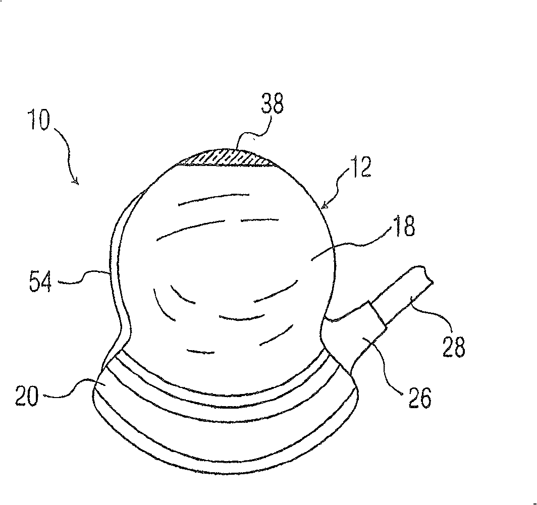
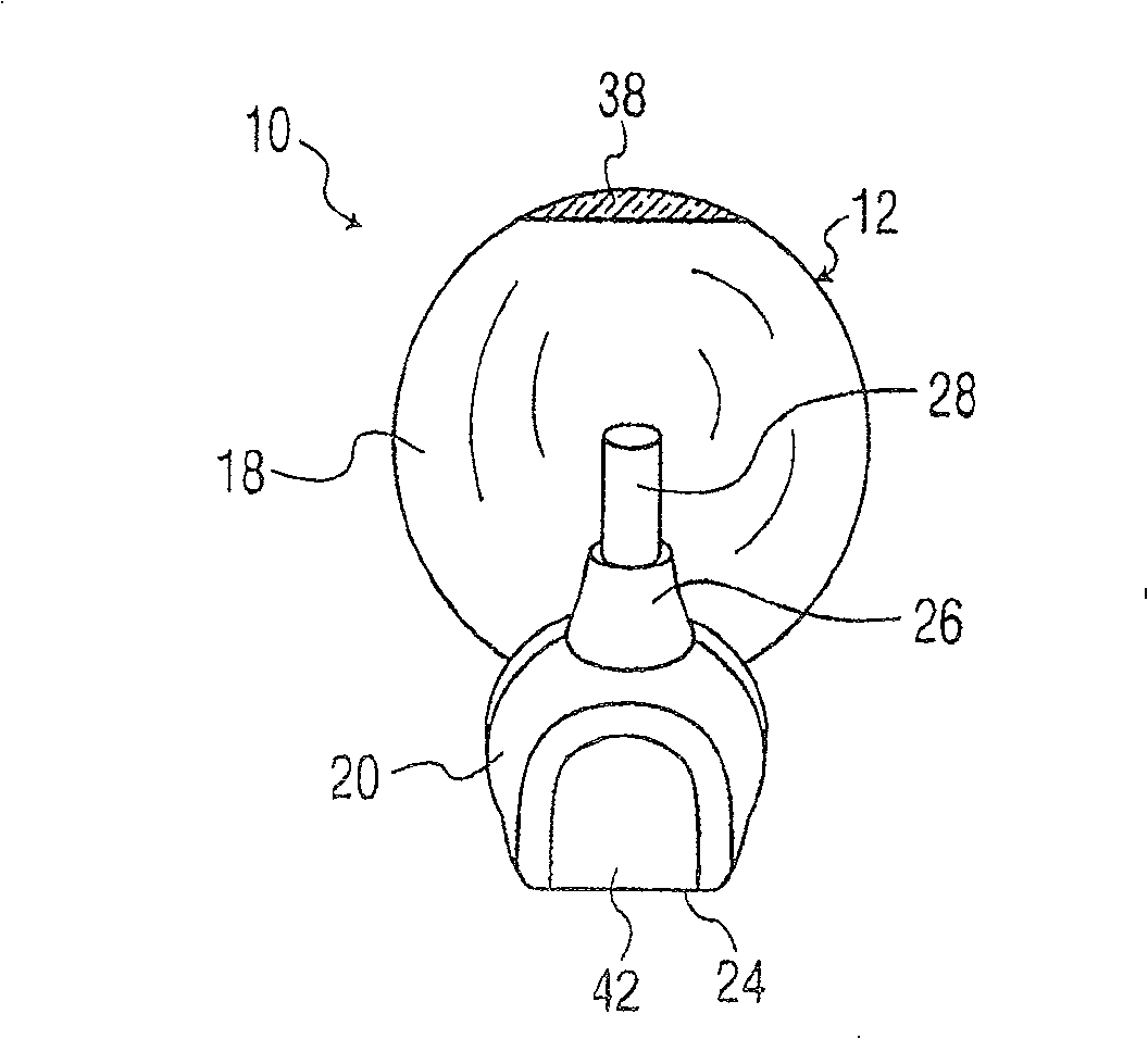
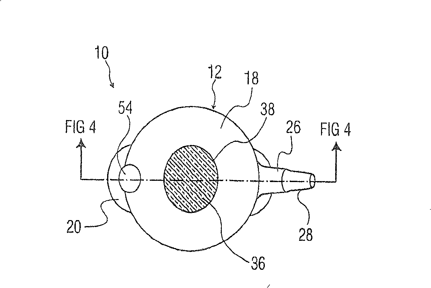
[0037] Referring to the drawings, in which like numerals indicate the same or similar elements, Figure 1 to Figure 5 An ultrasound transducer probe, indicated generally at 10, according to the invention is shown. The probe 10 includes a housing 12 , a transducer 14 disposed within the housing 12 and a display unit 16 disposed within the housing 12 . The display unit 16 may be built-in or integrated into the housing 12 .
[0038] The housing 12 has an upper portion 18 having a generally spherical outer surface and a lower portion 20 having an approximately frusto-conical general shape. The upper part 18 is designed to be easily grasped by a user and includes an opening 22 in its top part. The lower portion 20 includes an opening 24 through which ultrasonic waves are transmitted and received by the transducer 14 during use of the probe 10 . The lower portion 20 also includes a cable guide 26 through which cables 28 pass to connect the transducer 14 to a control unit (not sho...
PUM
 Abstract
Description
Claims
Application Information