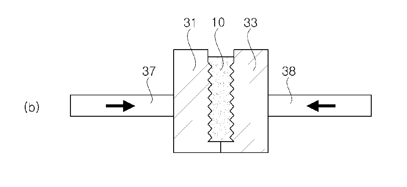
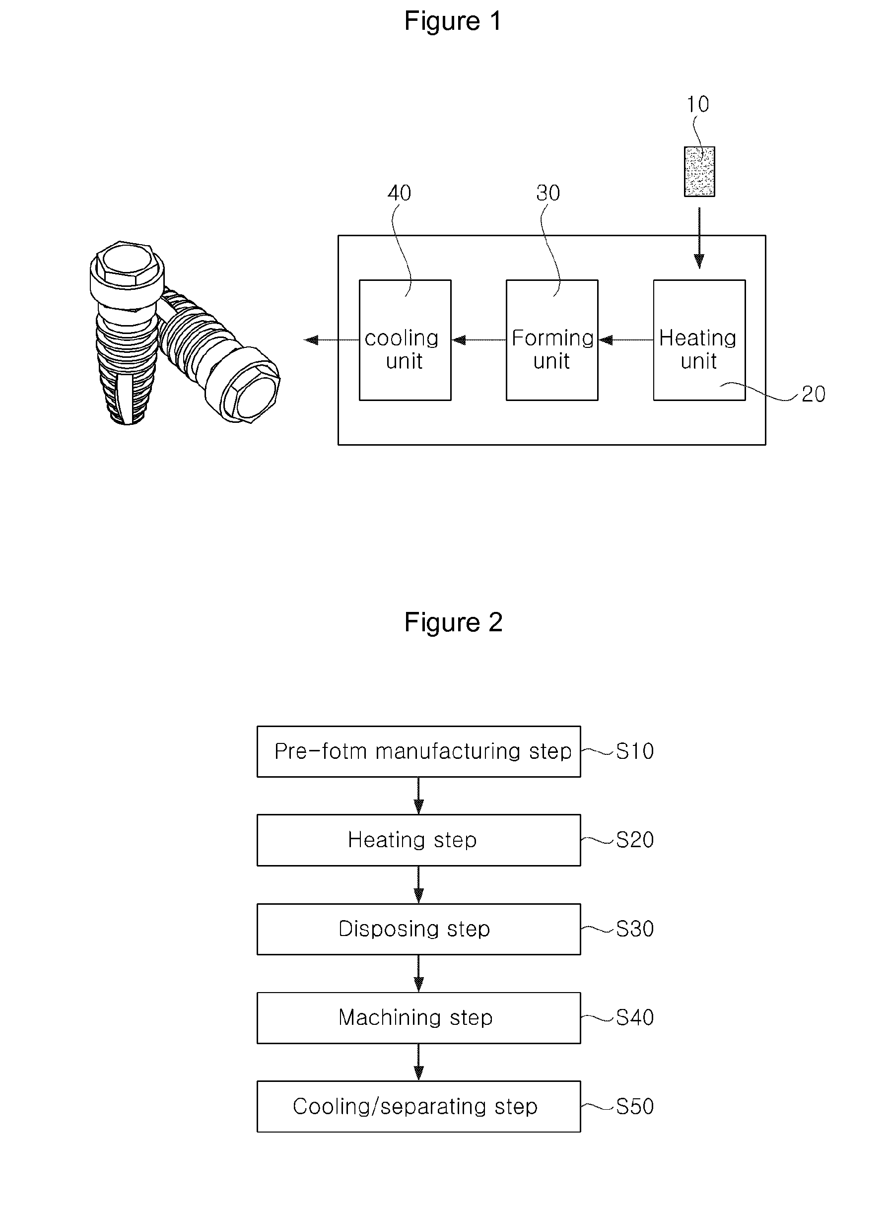
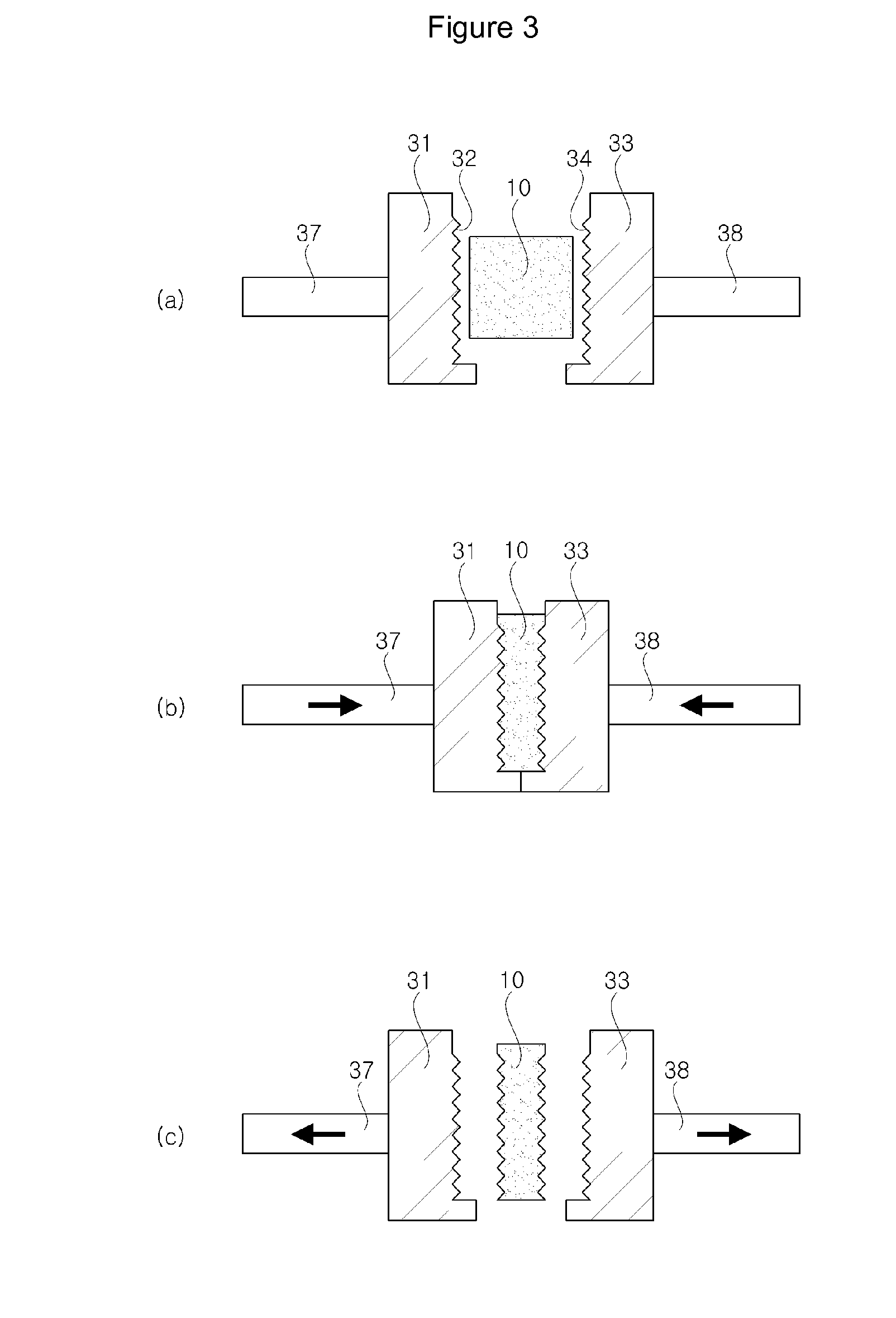
[0037]FIG. 1 is a diagram showing an apparatus for manufacturing an implant using an amorphous alloy according to an embodiment of the present invention. FIG. 2 is a flowchart showing a method for manufacturing an implant using an amorphous alloy according to an embodiment of the present invention. FIG. 3 shows illustrative views of a process of manufacturing an implant having a screw thread on an outer peripheral surface thereof by using the apparatus for manufacturing an implant according to the embodiment of the present invention. FIG. 4 shows illustrative views of a process of manufacturing an implant having screw threads on inner and outer peripheral surfaces thereof by using the apparatus for manufacturing an implant according to the embodiment of the present invention. FIG. 5 is a graph showing a thermoplastic forming process according to an embodiment of the present invention.
[0038]The present invention relates to an apparatus and a method for manufacturing an implant in a state in which a pre-form formed of an amorphous alloy is not fused into a liquid state but heated into a semi-solid state.
[0039]As shown in FIG. 1, the apparatus for manufacturing an implant using an amorphous alloy of the present invention includes a heating unit 20, a forming unit 30, and a cooling unit 40.
[0040]FIG. 1 shows separately the heating unit 20, the forming unit 30, and the cooling unit 40 separately, which may be installed in one unit.
[0041]That is, all of heating, forming, and cooling operations may be performed in one unit.
[0042]The heating unit 20 functions to heat a pre-form 10 formed of an amorphous alloy into a semi-solid state.
[0043]The heating unit 20 heats the pre-form 10 to a temperature higher than a glass temperature Tg shown in FIG. 5 and lower than a nose temperature Tn of the amorphous alloy to convert the pre-form 10 not into a liquid state but into a semi-solid state, that is, a state such as jelly.
[0044]The heating unit 20 preheats the pre-form 10 through a method such as high-frequency heating or heating by a heater.
[0045]The forming unit 30 functions to form a screw thread on the heated pre-form 10 by using a pressing mold.
[0046]As shown in FIG. 3, when a screw thread is to be formed on an outer peripheral surface of the pre-form 10, the forming unit 30 includes a first outer mold 31, a first cylinder 37, a second outer mold 33, and a second cylinder 38.
[0047]An inner surface of the first outer mold 31 is concavely recessed to have a first screw thread, and the second outer mold 33 is coupled to the first outer mold 31 and an inner surface of the second outer mold 33 is concavely recessed in a direction opposite to the first outer mold 31 to have a second screw thread 34.
[0048]The first cylinder 37 and the second cylinder 38 function to move the first outer mold 31 and the second outer mold 33, respectively.
[0049]The pre-form 10 heated into a semi-solid state is disposed between the first outer mold 31 and the second outer mold 33, and an external screw thread corresponding to the first screw thread 32 and the second screw thread 34 is formed on an outer peripheral surface of the pre-form 10.
[0050]As shown in FIG. 4, when screw threads are to be formed on an inner surface as well as an outer surface of the pre-form 10, the forming unit 30 further includes a core 35 and a third cylinder 39.
[0051]The core 35 is disposed between the first outer mold 31 and the second outer mold 33 and a third screw thread 36 is formed on an outer peripheral surface of the core 35. The third cylinder 39 functions to elevate the core 35 upward and downward while rotating the core 35.
[0052]The core 35 is inserted into an inner peripheral recess of the pre-form 10 disposed between the first outer mold 31 and the second outer mold 33 to form an internal screw thread corresponding to the third screw thread 36 on an inner peripheral surface of the pre-form 10.
[0053]The cooling unit 40 cools the pre-form10 in which a screw thread is formed by the forming unit 30 so that the pre-form 10 can be separated from the pressing mold.
[0054]Thermal expansion coefficients of the first outer mold 31 and the second outer mold 33 are preferably larger than a thermal expansion coefficient of the pre-form 10.
[0055]That is, when the first and second outer molds 31 and 33 and the pre-form 10 are heated or cooled, the first and second outer molds 31 and 33 are deformed further than the pre-form 10.
[0056]Further, the core 35 inserted into the inner peripheral recess of the pre-form 10 is rotated by the third cylinder 39 and extracted from the pre-form 10.
[0057]Hereinafter, a method for manufacturing an implant according to the present invention will be described.
[0058]The method for manufacturing an implant using an amorphous alloy according to the present invention includes a pre-form manufacturing step S10, a heating step S20, a disposing step S30, a machining step S40, and a cooling/separating step S50.
[0059]The pre-form manufacturing step S10 is a step of manufacturing a pre-form 10 in a state of an ingot having a predetermined size and a predetermined shape by using an amorphous alloy.
[0060]The heating step S20 is a step of heating the pre-form 10 into a semi-solid state by using the heating unit 20.
[0061]As shown in FIG. 5, in the heating step S20, the pre-form 10 is heated to a temperature higher than a glass temperature Tg and lower than a nose temperature Tn of the amorphous alloy.
[0062]Accordingly, the pre-form 10 formed of the amorphous alloy is converted into a state in which the pre-form 10 can be plastically machined.
[0063]The disposing step S30 is a step of disposing the pre-form 10 heated into a semi-solid state in the forming unit 30 for threading.
[0064]In more detail, as shown in FIGS. 3A and 4A, the heated semi-solid state pre-form 10 is disposed between the first outer mold 31 and the second outer mold 33.
[0065]Although the pre-form 10 is heated and then is disposed in the forming unit 30 in the embodiment of the present invention, the pre-form 10 may be first disposed in the forming unit 30 and then heated.
[0066]The machining step S40 is a step of forming a screw thread in the pre-form 10 disposed between the first outer mold 31 and the second outer mold 33 by the disposing step S30, by using the forming unit 30, that is, the pressing mold.
[0067]In the machining step S40, a screw thread is formed only on an outer peripheral surface of the pre-form 10 as shown in FIG. 3B or screw threads are formed on both an outer peripheral surface and an inner peripheral surface of the pre-form 10 as shown in FIG. 4B.
[0068]As shown in FIG. 3B, when a screw thread is to be formed only on an outer peripheral surface of the pre-form 10, the first outer mold 31 and the second outer mold 33 are moved to press the pre-form 10 disposed therebetween by using the first cylinder 37 and the second cylinder 38.
[0069]Accordingly, an external screw thread corresponding to the first screw thread 32 and the second screw thread 34 are formed on an outer peripheral surface of the pre-form 10.
[0070]Further, as shown in FIG. 4B, when screw threads are to be formed on both an inner peripheral surface and an outer peripheral surface of the pre-form 10, the core 35 is first inserted into an inner peripheral recess of the pre-form 10 by using the third cylinder 39, and the first outer mold 31 and the second outer mold 33 are moved to press the pre-form 10 disposed therebetween by using the first cylinder 37 and the second cylinder 38.
[0071]Accordingly, an external screw thread corresponding to the first screw thread 32 and the second screw thread 34 is formed on an outer peripheral surface of the pre-form 10, and an internal screw thread corresponding to the third screw thread 36 is formed on an inner peripheral surface of the pre-form 10.
[0072]Then, as shown in FIG. 5, since the machining step S40 is performed while the pre-form 10 is heated to a temperature higher than the glass temperature and lower than the nose temperature, the pre-form 10 is plastically deformed to have an external screw thread and/or an internal screw thread.
[0073]As shown in FIG. 5, the cooling/separating step S50 is a step of cooling the pre-form 10 having a screw thread below a glass temperature to separate the pre-form 10 from the pressing mold, that is, the forming unit 30.
[0074]In the cooling/separating step S50, the pressing mold and the pre-form 10 are separated from each other by using the thermal expansion coefficients of the pressing mold and the pre-form 10.
[0075]That is, the thermal expansion coefficients of the first outer mold 31, the second outer mold 33, and the core 35 are larger than the thermal expansion coefficient of the pre-form 10 formed of an amorphous alloy.
[0076]Accordingly, if the first outer mold 31, the second outer mold 33, the core 35, and the pre-form 10 are cooled together in the cooling/separating step S50, the first outer mold 31, the second outer mold 33, and the core 35 are contracted further than the pre-form 10, so that the pre-form 10 can be naturally separated form the first outer mold 31, the second outer mold 33, and the core 35.
[0077]Thereafter, as shown in FIGS. 3C and 4C, the first outer mold 31 and the second outer mold 33 are moved by using the first cylinder 37 and the second cylinder 38 so that the pre-form having the screw thread, that is, the implant can be extracted.
[0078]Further, as shown in FIG. 4, when an internal screw thread is formed on an inner peripheral surface of the pre-form 10 by using the core 35, the core 35 is separated from the pre-form 10 while the core 35 is rotated by using the third cylinder 39 as shown in FIG. 4C, and the first outer mold 31 and the second outer mold 33 are moved to extract the pre-form 10 having an internal screw thread and an external screw thread, that is, the implant.
[0079]According to the apparatus and method of the present invention, an implant having a screw thread on an inner peripheral surface and/or an outer peripheral surface thereof can be manufactured of an amorphous alloy by using pressing instead of die casting.
[0080]The apparatus and method for manufacturing an implant using an amorphous alloy of the present invention are not limited to the embodiments, but may be variously modified without departing from the spirit of the present invention.
[0081]According to the present invention, an implant having a screw thread on an inner peripheral surface and/or an outer peripheral surface thereof can be manufactured of an amorphous alloy by using pressing instead of die casting.