Cutter for cutting band material, particularly textile- or steel-cord bands

A technology of cutting device and cutting belt, which is applied in the direction of shearing device, application, household appliances, etc., and can solve the problem of joint strength reduction

Active Publication Date: 2007-09-26
KARL EUGEN FISCHER
View PDF0 Cites 23 Cited by
  • Summary
  • Abstract
  • Description
  • Claims
  • Application Information

AI Technical Summary

Problems solved by technology

However, if the material is cut through with a round knife, the achievable joint strength is reduced compared to a hook knife

Method used


Image

  • Cutter for cutting band material, particularly textile- or steel-cord bands
  • Cutter for cutting band material, particularly textile- or steel-cord bands
  • Cutter for cutting band material, particularly textile- or steel-cord bands

Examples


Embodiment Construction

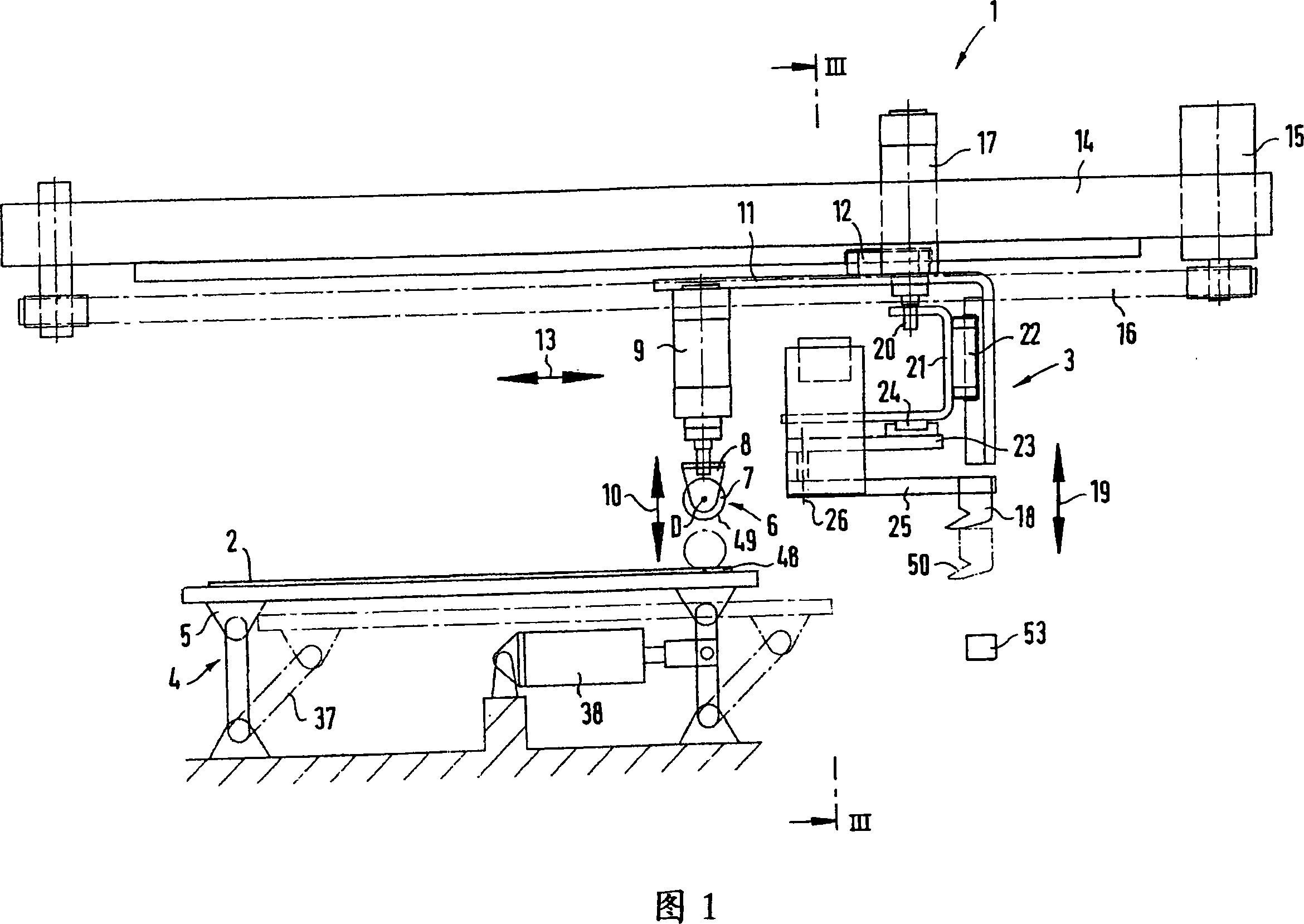
[0029] Figure 1 shows a cutting device 1 for cutting fabric or cord tape material 2 according to the invention, which comprises a cutting structure 3 and a table 4 supporting the tape material, for the sake of clarity only the said The table section 5, which can be swung by the table, will be described below. The cutting structure includes a circular knife 6 , shown here as a circular circular knife 7 . The circular knife 7 is arranged in a knife holder 8, wherein the circular knife is rotatable about an axis of rotation D and can be moved along this axis preferably against the restoring force of two tensioning springs acting laterally, so that at the same time the Axial movability perpendicular to the cutting direction is achieved. The two tensioning springs, not shown in detail, center the circular knife 7 relative to the shaft. Circular knife 7 can move vertically by a lifting device 9, as shown by double arrow 10. The lifting device 9 can be a hydraulic or pneumatic cyl...


PUM

PropertyMeasurementUnit
lengthaaaaaaaaaa

Abstract

The invention relates to a cutting device for cutting strip material, in particular textile or steel rope strips, comprising a cutting device for moving relative to static strip material, wherein the said cutting device is composed of cutter (6) for generating precut with brim side, with circular cutting blade (48) and a bush hook (18) connecting with the back of the said circular cutter and cutting into the precut and through cutting strip material (2), or is composed of only one double-point tool (56) with a arc cutting blade (63) and a hook cutting blade (64).

Description

technical field [0001] The invention relates to a cutting device for cutting strip material, in particular fabric or steel cord strip, comprising a cutting structure movable relative to the stationary strip material. Background technique [0002] In tire production, fabric or steel cord belt material with fabric or steel wires / cords (faden) as embedded structures must be cut longitudinally along the wires and then rejoined. If, after the cutting process, a butt joint is required as a butt joint in which the edges of the strips to be connected touch each other, i.e. do not overlap each other, and this butt joint should have high strength, then it must be required that, in the previous material cutting, the same The wires are parallel and no fabric or steel wires are exposed at the two cut edges. Because otherwise the joint connection would not have sufficient strength, since only less rubber to be joined is present directly in the region of the joint seam. Because the stren...

Claims


Application Information

Patent Timeline
Patent Type & Authority Applications(China)
IPC IPC(8): B26D9/00B26D1/18B26D1/10B26D1/45B26D7/26B26D7/10B26D7/14B26D7/01B26D7/20
CPCB26D1/0006B26D1/04B26D1/18B26D9/00B26D2001/004B26D2001/006B29D30/46B23D15/00B26D1/06
Inventor R·克勒纳B·霍夫曼
Owner KARL EUGEN FISCHER
Why Eureka
Try Eureka