Permanent Magnet Synchronous Motor Servo System and Positioning and Deviation Elimination Method
A permanent magnet synchronous motor and servo system technology, applied in the direction of electrical components, electromechanical devices, electric components, etc., can solve the problems of large rotor rotation range, small motor electromagnetic torque, mechanical impact, etc. The method is simple and fast, and the rotor rotation The effect of small movements and high positioning accuracy
- Summary
- Abstract
- Description
- Claims
- Application Information
AI Technical Summary
Problems solved by technology
Method used
Image
Examples
Embodiment 1
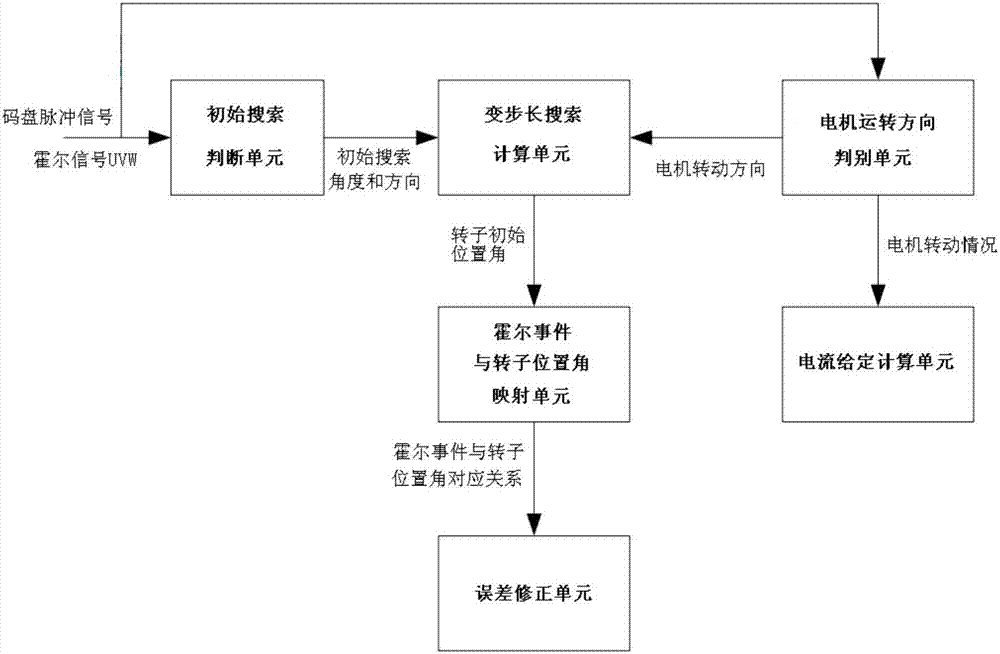
[0064] The servo system of the permanent magnet synchronous motor of the present invention is based on a hybrid incremental encoder. When the code disc of the hybrid incremental encoder rotates, a code disc pulse signal and a Hall signal are generated. Refer to figure 1 , the servo system of the present invention comprises:
[0065] The initial search judgment unit judges the initial search angle and direction according to the Hall signal; the motor running direction judgment unit judges the motor rotation direction according to the code disc pulse signal; the variable step search calculation unit is connected with the initial search judgment unit and the motor running direction judgment The unit is connected to search out the rotor initial position angle of the permanent magnet synchronous motor according to the initial search angle and direction and the motor rotation direction, so as to locate the permanent magnet synchronous motor; Hall event and rotor position angle mappin...
Embodiment 2
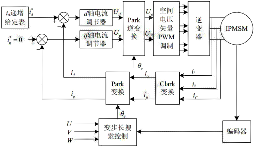
[0068] refer to Figure 2 to Figure 9 , the specific embodiment of the positioning and deviation elimination method of the permanent magnet synchronous motor of the present invention is:
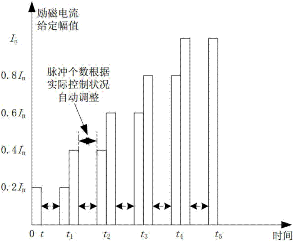
[0069] This embodiment adopts the built-in permanent magnet synchronous motor (IPMSM), utilizes the current-speed-position three-loop system control, preferably adopts the current closed-loop control structure in the process of positioning the initial position of the rotor, that is, closes the position loop of the three-loop system and speed loop, only the current loop is reserved, the specific control structure block diagram is as follows figure 2 shown. figure 2 i in d Incrementing the given table is image 3 The excitation current shown (i d ) pulse given mode, i d * is a current given excitation current, i q * is a current given torque current; the d-axis current regulator and the q-axis current regulator are respectively the excitation current i d where the d-axis and the tor...
PUM
 Abstract
Description
Claims
Application Information
 - R&D
- Intellectual Property
- Life Sciences
- Materials
- Tech Scout
- Unparalleled Data Quality
- Higher Quality Content
- 60% Fewer Hallucinations
Browse by: Latest US Patents, China's latest patents, Technical Efficacy Thesaurus, Application Domain, Technology Topic, Popular Technical Reports.
© 2025 PatSnap. All rights reserved.Legal|Privacy policy|Modern Slavery Act Transparency Statement|Sitemap|About US| Contact US: help@patsnap.com


