Eureka AIR delivers breakthrough ideas for toughest innovation challenges, trusted by R&D personnel around the world.

Lighting fixture

A lighting device and light-emitting device technology, which is applied in the direction of lighting devices, non-electric lighting devices, lighting and heating equipment, etc., can solve the problems of cost increase and achieve the effect of low cost

Inactive Publication Date: 2007-09-26
HONG FU JIN PRECISION IND (SHENZHEN) CO LTD +1
View PDF0 Cites 4 Cited by
  • Summary
  • Abstract
  • Description
  • Claims
  • Application Information

AI Technical Summary

Problems solved by technology

Because the lighting device needs to go through the process of converting sunlight into electrical energy and then from electrical energy to light energy, it needs to introduce expensive equipment such as solar panels and batteries in the middle. Compared with the lighting device that directly uses sunlight, its cost is greatly increased

Method used


Image

  • Lighting fixture

Examples


Embodiment Construction

[0009] The lighting device of the present invention will be further described in detail below with reference to the drawings and embodiments.

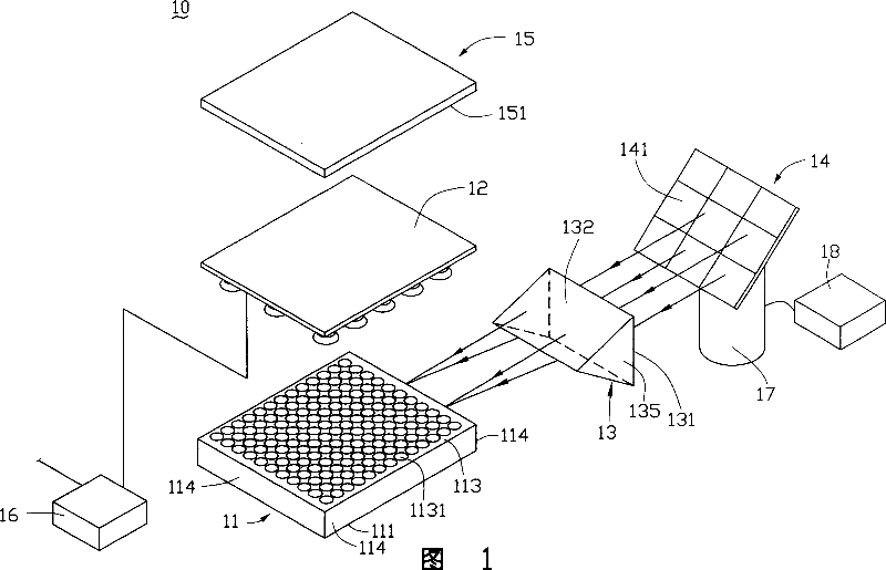
[0010] Please refer to FIG. 1 , which is a preferred embodiment of the lighting device of the present invention. The lighting device 10 includes a light guide plate 11 , a triangular prism 13 and a light reflecting device 14 .

[0011] The light guide plate 11 is a square plate, which includes a light emitting surface 111 , a bottom surface 113 and four sides 114 . The bottom surface 113 is opposite to the light-emitting surface 111 , and the four side surfaces 114 are between the light-emitting surface 111 and the bottom surface 113 and connect the light-emitting surface 111 and the bottom surface 113 . A plurality of dot arrays 1131 are disposed on the bottom surface 113 . The triangular prism 13 includes three side surfaces and two end surfaces 135 , one of which is a light-incoming surface 131 , and the other two sides connected ...


PUM


Abstract

A lighting device comprises a guide plate, a light concentrating component and a light reflective device. The guide optical plate has an light output face with the light concentration component set at one side of the guide optical plate. The reflective optical device is used to receive the solar beam and reflected it to the light concentration component, and the light concentration component integrated the beam and guided it into the guide optical plate and to the output optical plate. It is cheap in cost.

Description

【Technical field】 [0001] The invention relates to a lighting device. 【Background technique】 [0002] With the development of society, large-scale buildings are constantly appearing, which generally have a larger area, and it is difficult for the central position to receive external natural light, so it is also necessary to use lighting devices for lighting during the day. Most of the current lighting devices are electric lighting, and most of the existing electricity is obtained by utilizing non-renewable energy sources such as petroleum and coal. For this reason, someone has proposed the illuminating device that utilizes sunlight. [0003] Existing lighting devices that use sunlight generally include solar panels, batteries, and light-emitting devices. They use solar panels to first collect sunlight and convert it into electrical energy, and then store the resulting electrical energy through the battery, and then send it to the light-emitting device through the battery. P...

Claims


Application Information

Patent Timeline
Patent Type & Authority Applications(China)
IPC IPC(8): F21S11/00F21S2/00F21Y113/02F21Y113/20
Inventor 张佳煌
Owner HONG FU JIN PRECISION IND (SHENZHEN) CO LTD
Why Eureka
Eureka Blog
Learn More