Scanner capable of preventing vacuum adsorption phenomenon and cover-lift structure

A scanner and cover structure technology, applied in image communication, electrical components, etc., can solve problems such as out-of-focus blurred images, inability to effectively flatten manuscripts, etc.

Inactive Publication Date: 2007-09-26
BENQ CORP
View PDF0 Cites 3 Cited by
  • Summary
  • Abstract
  • Description
  • Claims
  • Application Information

AI Technical Summary

Problems solved by technology

[0007] However, since the edge of the sheet 18 is bent and extended to the top of the upper cover 21 of the scanner body, at the edge adjacent to the opening 21a, the sheet 18 cannot effectively flatten the document, which may cause the scanned image to be out of focus and blurred. Phenomenon

Method used


Image

  • Scanner capable of preventing vacuum adsorption phenomenon and cover-lift structure
  • Scanner capable of preventing vacuum adsorption phenomenon and cover-lift structure
  • Scanner capable of preventing vacuum adsorption phenomenon and cover-lift structure

Examples


Embodiment Construction

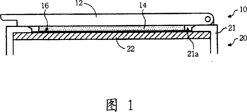
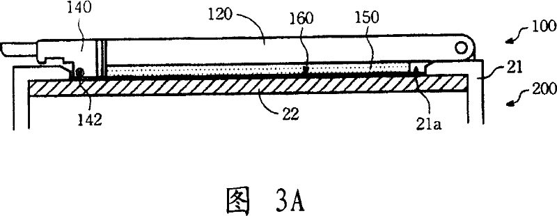
[0038] Please refer to Figure 3A. This figure is a schematic diagram of a preferred embodiment of the scanner of the present invention. As shown in the figure, the scanner is composed of a scanner body 20 and a clamshell structure 100 . Wherein, the scanner body 20 has an upper cover 21 and a glass bottom plate 22 . The upper cover 21 is formed with an opening 21a, and the glass bottom plate 22 is installed in the opening 21a from bottom to top to carry manuscripts. The cover structure 100 is pivotally connected to the scanner body 20 through a rotating shaft, so as to cover the document on the glass bottom plate 22 .

[0039] Please also refer to FIG. 3B . This figure is an exploded view of the clamshell structure 100 shown in FIG. 3A . As shown in this figure, the flip structure 100 has a flip body 120 , a compressible material layer 150 , a sheet 160 and a handle 140 . Wherein, the rear side 120 b of the clamshell body 120 has a first pivot portion 122 for pivotally co...


PUM


Abstract

The disclosed lift-cover structure for scanner comprises: a lift-cover body with compressible material layer on lower side for even compressing the manuscript, a thin sheet on bottom surface of the material layer to flatten the manuscript, and a handle linked with the lift-cover body side and connected with edge of the sheet top surface. This invention trips the handle to extrude air into the room between the sheet and glass bottom, can avoid hard lifting as adsorption, and also flattens the manuscript effectively to ensure scanning quality.

Description

technical field [0001] The invention relates to a scanner and its cover structure, in particular to a scanner and its cover structure capable of preventing vacuum adsorption. Background technique [0002] For early computer users, scanners were rare peripherals. Due to the high price and difficult operation of early scanners, they are usually only used in professional digital image processing work. However, with the development of digital imaging technology, many cheap and easy-to-use scanners have flooded into the market. Over the past few years, they have become an integral part of personal or small office computer systems. [0003] Please refer to Figure 1. FIG. 1 is a schematic cross-sectional view of a flip cover 10 of a conventional scanner. As shown in this figure, the flip cover 10 is pivotally connected to the main body 20 of the scanner. The upper cover 21 of the scanner body 20 is formed with an opening 21a, and the glass bottom plate 22 is installed in the o...

Claims


Application Information

Patent Timeline
Patent Type & Authority Applications(China)
IPC IPC(8): H04N1/04H04N1/10
Inventor 陈义松
Owner BENQ CORP
Why Eureka
Try Eureka