Open spinning machine with pipe joint

A technology for pipe joint and start spinning, which is applied to open-end spinning machines, spinning machines, spinning machines with continuous winding, etc., and can solve problems such as restarting

Active Publication Date: 2011-04-20
RIETER INGOLSTADT SPINNEREI
View PDF0 Cites 0 Cited by
  • Summary
  • Abstract
  • Description
  • Claims
  • Application Information

AI Technical Summary

Problems solved by technology

Even under normal conditions, there is an additional safety risk in dismantling pipe joints with the cover member open and the rotor stopped, that is, when the cover member is closed, the open-end spinning machine may not fit in the pipe joint. or is restarted without a secure fix

Method used


Image

  • Open spinning machine with pipe joint
  • Open spinning machine with pipe joint
  • Open spinning machine with pipe joint

Examples


Embodiment Construction

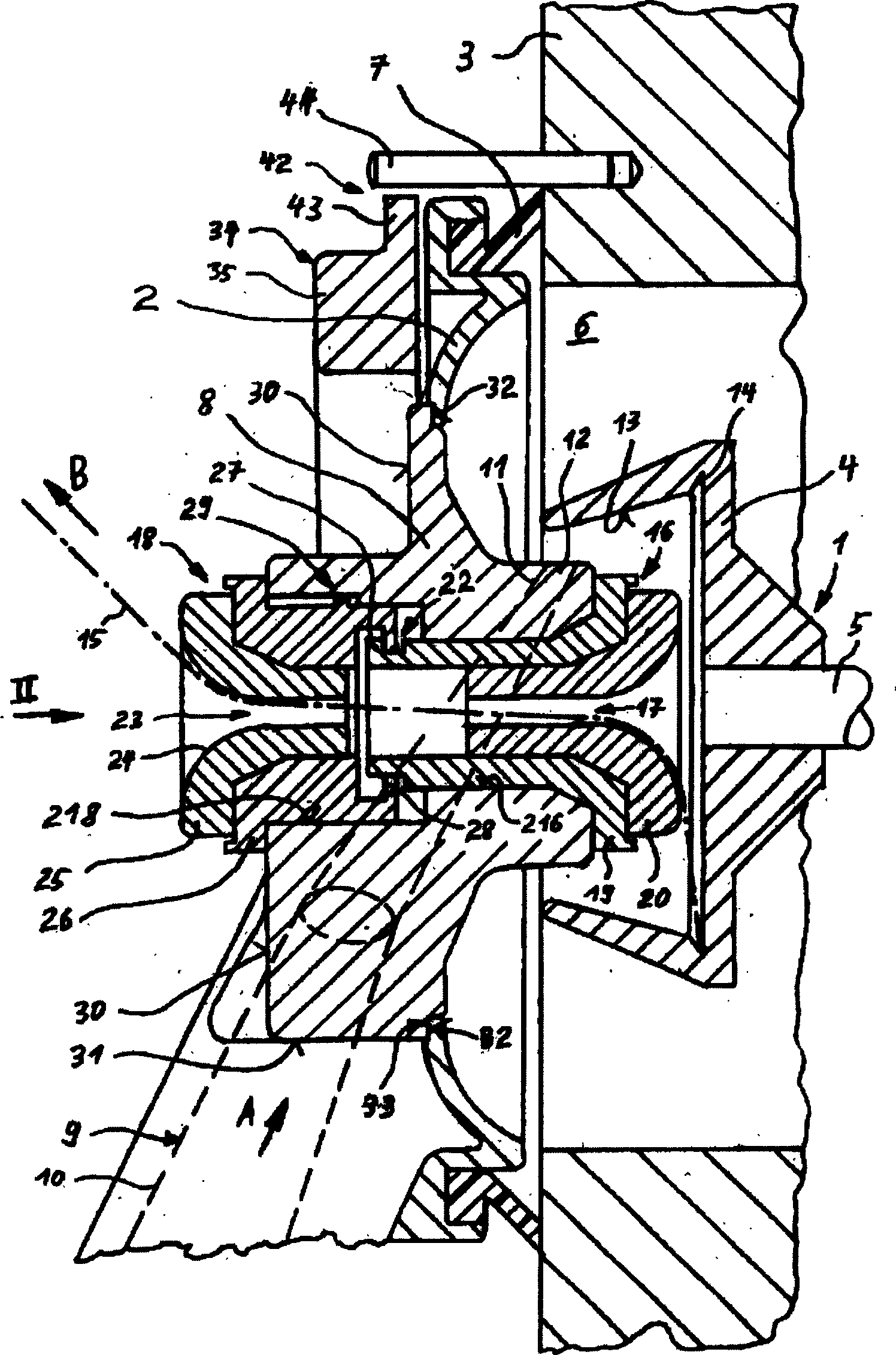
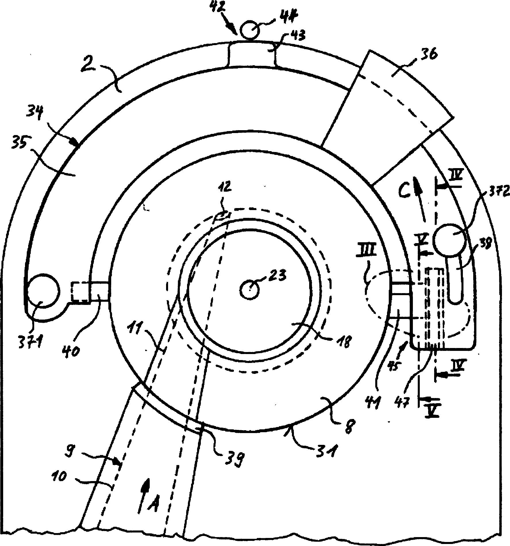
[0028] exist figure 1 and figure 2 The figure shows a rotor device 1 enclosed in a rotor housing 3 by a cover member 2 on an open-end spinning machine. The cup rotor 1 is formed in a known manner from a rotor cup 4 and a shaft 5 mounted and driven in any manner not shown in the figures.

[0029] During spinning, the rotor 4 rotates in a known manner in a negatively pressurized interior 6 formed by the rotor housing 3 . During spinning, the rotor housing 3 is closed with a cover element 2 which can be removed for maintenance purposes. The annular sealing ring 7 is used for sealing between the cover member 2 and the rotor housing 3 .

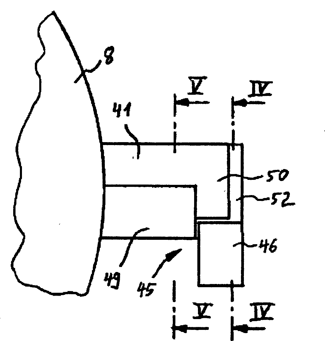
[0030]Arranged on the cover part 2 , which is often also referred to as the bezel, is an easily replaceable line connection 8 , which has a shoulder protruding into the interior of the rotor cup 4 . The fiber feed channel 9 extends in a known manner from an opening roller, not shown, to the rotor cup 4 . The fiber feed channel 9 is shown in ...


PUM


Abstract

A rotary rotor device is arranged in the rotor shell of an open end spinning machine. An enclosing cover component used for enclosing the rotor shell is preinstalled, wherein a channel joint can be loaded. At least one blocking element is preinstalled to prevent the open end spinning machine starting operation. A blocking element can be preinstalled to prevent from unloading the channel joint when the rotor device is in operation. In addition, another blocking element can be preinstalled to avoid and close the enclosing cover component when the channel joint is not installed. A fixed device including at least one blocking element can be installed for the changeable channel joint in the enclosing cover component. The channel joint had better include a bushing for the use of yarn take-off nozzle and a bushing used for rotation keeping part and the exterior profile a circular outer contour with two diametrically opposite projections.

Description

technical field [0001] The invention relates to an open-end spinning machine with a rotor and a cover member, wherein the rotor is rotatably arranged in a rotor housing, and the cover member closes the rotor housing and includes a Loadable pipe fittings. [0002] The invention also relates to a pipe joint suitable for such an open-end spinning machine. Background technique [0003] The state of the art of an open-end spinning machine with such a pipe joint is derived from German patent publication 21 30 582 . Wherein said pipe joint basically adopts a kind of strong cylinder form, and it has two holes that are not on a plane with each other, wherein one hole is used as fiber feeding channel hole, and another hole is used as doffing channel hole. The pipe joint is placed on the surface of the cylindrical shell of the closure member and secured to the closure member by a threaded pin radially tightened on the surface of the cylindrical shell. There are absolutely no preset ...

Claims


Application Information

Patent Timeline
Patent Type & Authority Patents(China)
IPC IPC(8): D01H4/08
CPCD01H4/44D01H4/40
Inventor M·布尔歇特S·克罗默尔
Owner RIETER INGOLSTADT SPINNEREI
Why Eureka
Try Eureka