Method for building railway bridge and simple support T beam bridge

A railway bridge and simply supported technology, applied in bridges, bridge materials, bridge construction, etc., can solve problems such as unsatisfactory, cumbersome horizontal connection process, and restricted beam erection speed

Active Publication Date: 2007-10-10
CHINA RAILWAY ENG CONSULTING GRP CO LTD
View PDF0 Cites 14 Cited by
  • Summary
  • Abstract
  • Description
  • Claims
  • Application Information

AI Technical Summary

Problems solved by technology

The disadvantages are: the horizontal connection process is cumbersome, which restricts the speed of girder erection; when a bridge uses porous beams, ballast and rails need to be temporarily laid on the erected beams, which further restricts the speed of girder erection
The pavement slabs are laid on the angle steel supports, resulting in no space for cable trays, sound barriers and catenary columns, which cannot meet the needs of ancillary facilities on the railway bridge

Method used


Image

  • Method for building railway bridge and simple support T beam bridge
  • Method for building railway bridge and simple support T beam bridge
  • Method for building railway bridge and simple support T beam bridge

Examples


Embodiment Construction

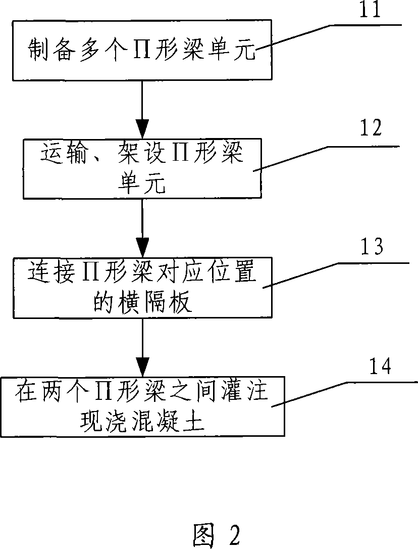
[0029] Fig. 2 is the flow chart of the embodiment of the method for erecting simply supported T-beam bridge of the present invention, and present embodiment is used for erecting double-track railway bridge, specifically comprises the following steps:

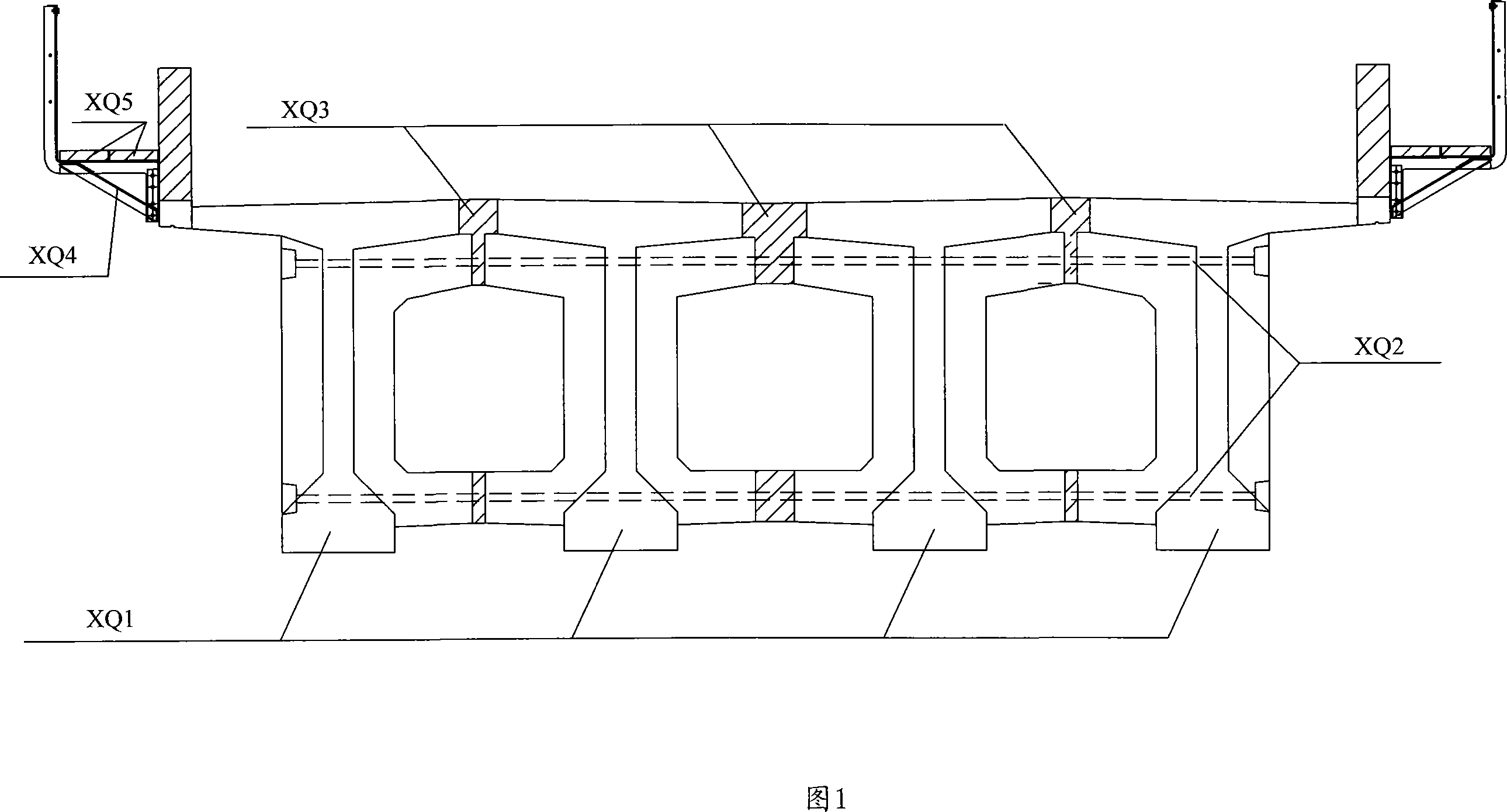
[0030] Step 11, preparing multiple ∏-shaped beam units. Assuming that the double-track railway bridge is a bridge with 10-hole beams, 20 ∏-shaped beam units need to be prepared. Firstly, connect two simply-supported T-beam decks and diaphragms horizontally under the bridge, and stretch the prestressed tendons of the diaphragms to form a ∏-shaped beam unit; the specific steps are as follows:

[0031] Under the bridge, place the two simply supported T-beams in accurate alignment according to the size set at the relative position during erection;

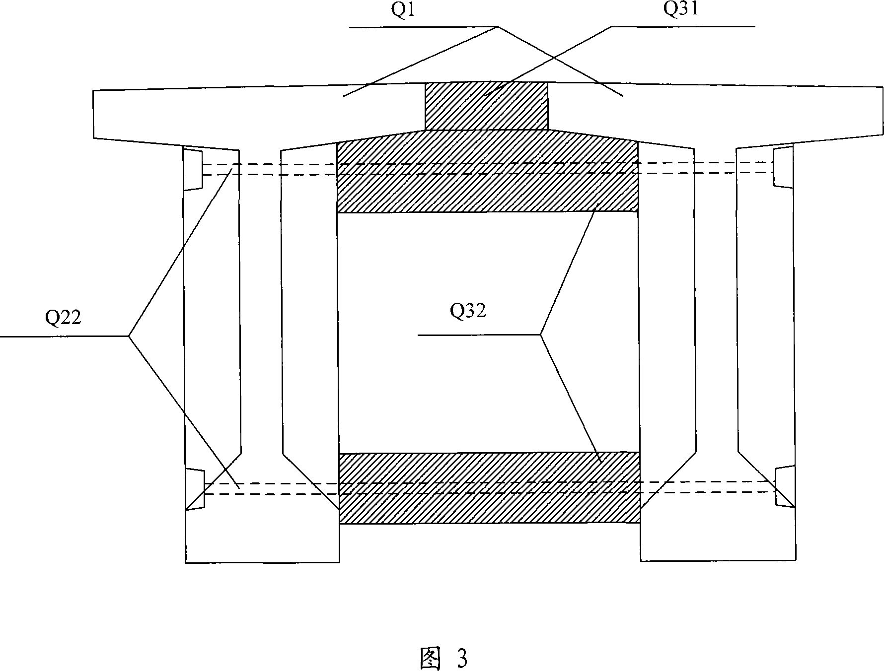
[0032] Bind the connecting steel bars of the diaphragm at the corresponding positions of the two simply supported T-beams and the connecting steel bars of the bridge deck, and connect th...


PUM


Abstract

The present invention relates to a method for erecting railway bridge and a simply-supported T-beam bridge. Said erection method includes the following steps: preparing inverted 'U'-shaped beam unit under the bridge, then transporting and placing all the inverted 'U'-shaped beam units, and transverse connecting all the inverted 'U'-shaped beam units so as to implement erection of simply-supported T-beam bridge.

Description

technical field [0001] The invention relates to a railway bridge technology, in particular to a method for erecting a railway bridge and a simply supported T-beam bridge. Background technique [0002] In railway bridges, simply supported T-beam bridges made of simply supported T-beams are used, and each bridge is composed of multiple pieces of simply supported T-beams. [0003] The erection process of the simply supported T-beam bridge is as follows: after the simply supported T-beams are prefabricated piece by piece, the simply supported T-beams are transported piece by piece to the bridge head through the existing railway line by using a special railway girder truck, and then the wheel-rail type is used to The bridge erecting machine erects the girder piece by piece. When erecting beams, accurately place two (or four) simply supported T-shaped beams on the beam pedestal, and temporarily connect the beams in place horizontally to ensure the stability of the bridge erecting...

Claims


Application Information

Patent Timeline
Patent Type & Authority Applications(China)
IPC IPC(8): E01D2/00E01D101/24
Inventor 徐升桥刘玉亮李国强沈平邓运清侯建军
Owner CHINA RAILWAY ENG CONSULTING GRP CO LTD
Why Eureka
Try Eureka