Double rail supporting table type rail transit U-shaped beam

A rail transit and rail bearing platform technology, applied in bridges, bridge construction, erection/assembly of bridges, etc., can solve the problems of increased land occupation and the inability of small U beams to be suitable for wiring sections, etc., to reduce occupation, facilitate construction, The effect of expanding the scope of application

Inactive Publication Date: 2014-06-11
CHINA RAILWAY ENG CONSULTING GRP CO LTD
View PDF6 Cites 1 Cited by
  • Summary
  • Abstract
  • Description
  • Claims
  • Application Information

AI Technical Summary

Problems solved by technology

[0007] The purpose of the present invention is to provide a U-shaped beam for double-supporting platform rail transit, and propose a large U-shaped beam structu

Method used


Image

  • Double rail supporting table type rail transit U-shaped beam
  • Double rail supporting table type rail transit U-shaped beam
  • Double rail supporting table type rail transit U-shaped beam

Examples


Embodiment 1

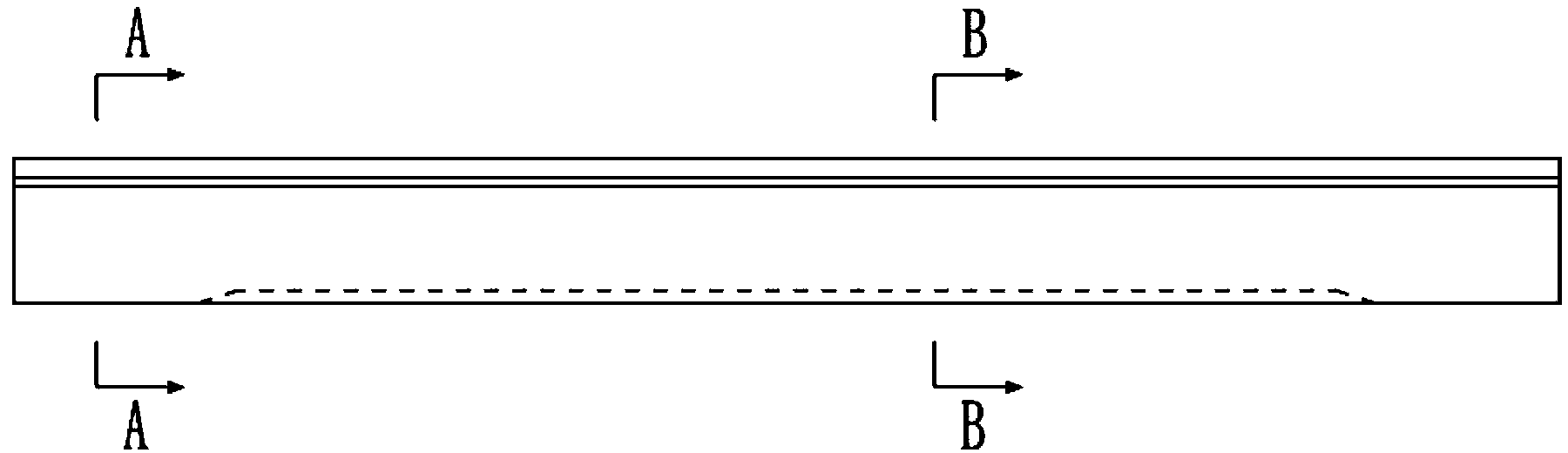
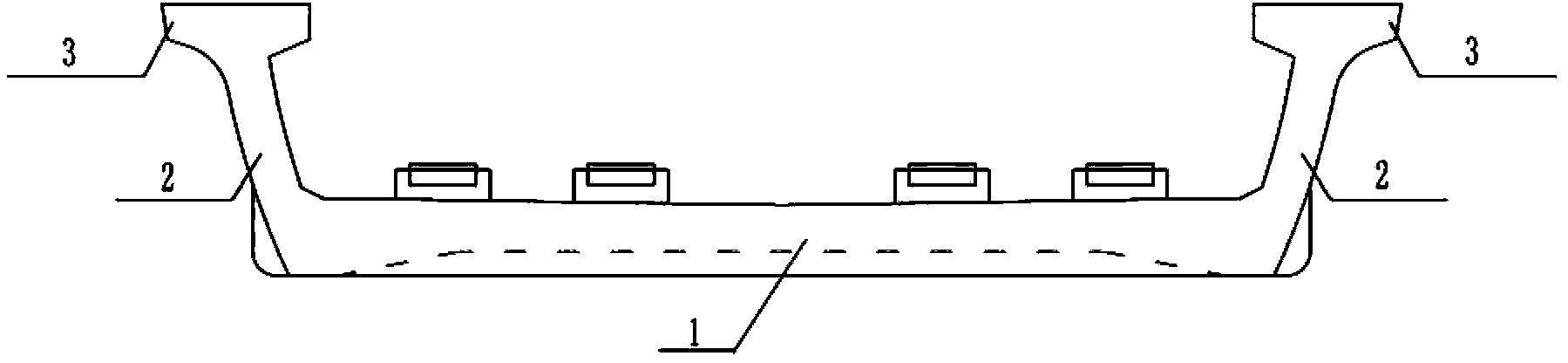
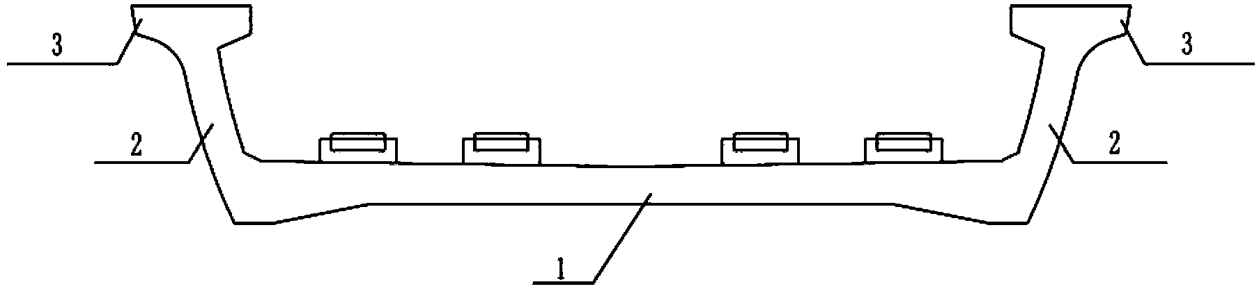
[0039] Such as Figure 4 As shown, the U-shaped rail transit U-beam with double bearing rails according to the present invention includes a beam body composed of a bottom plate 1, two side webs 2 and a flange plate 3 at the top of the web 2, and the upper surface of the bottom plate 1 is connected to the bearing The rail platform 5 is fixedly connected with a power supply device 8 along the length of the flange plates 3 on both sides, and the inner side of the web 2 is respectively provided with brackets 6 for supporting power supply cables, and the bottom plate 1 is provided with a cable groove 7; figure 1 As shown, the beam body in this embodiment has a continuous U-shaped cross-section, and there are at least two pairs of rail-supporting platforms 5 .

[0040] The U-shaped beam structure in this embodiment is a double-track rail transit U-shaped beam, which is different from the single-track U-shaped (small U-shaped beam) double-track railway that needs to use two beam bodi...


PUM


Abstract

The invention discloses a double rail supporting table type rail transit U-shaped beam. The double rail supporting table type rail transit U-shaped beam comprises a beam body which is composed of a bottom plate, two side web plates and two flange plates at the tops of the web plates. The supper surface of the bottom plate is connected with rail supporting tables, power supply devices are fixedly connected along the length direction of the two flange plates, the inner sides of the web plates are provided with supports for supporting power supply cables, and the bottom plate is provided with cable grooves; the cross section of the beam body is in a U shape, and the number of the rail supporting table is at least two pairs. The double rail supporting table type rail transit U-shaped beam is in a large beam structure and accordingly solves the problem that a small U-shaped beam cannot be applied to a cable distribution interval, widens the application range of U-shaped beams, better improves the landscape effects of urban bridges, reduces the noise of rail transit, and meanwhile, avoids increase of inter-cable distance of small U-shaped beams and reduces occupation of land resources. The double rail supporting table type rail transit U-shaped beam achieves one beam for one double-cable hole, increases the construction speed of U-shaped beams, shortens the engineering period and is applicable to popularization and application.

Description

technical field [0001] The invention relates to an elevated bridge track bed supporting member for supporting rails, in particular to a U-shaped beam of double-rail-supporting platform rail transit. Background technique [0002] Traditional viaducts generally use top-through box-section members or T-section members to support the track. The disadvantages are that the overall height of the building is large, the space utilization rate is low, and the scalability is not strong. [0003] Chinese application 200810304445.3 discloses a U-shaped beam for urban rail transit. The beam body is connected by the bottom plate, the webs on both sides and the flange plate on the top of the web to form a U-shaped cross-section channel. The upper surface of the bottom plate is connected to the rail platform. A power supply device, a power supply cable support body and a communication signal cable support body are fixedly connected along the length of the beam body. The webs on both sides ar...

Claims


Application Information

Patent Timeline
IPC IPC(8): E01D2/00E01D21/00
Inventor 徐升桥柳学发邓运清张付宾田杨薛洪卫李辉梁磊
Owner CHINA RAILWAY ENG CONSULTING GRP CO LTD
Why Eureka
Try Eureka