Endoscope shape detecting apparatus
A detection device and endoscope technology, which can be used in telescopes, diagnostic recording/measurement, medical science, etc., and can solve problems such as spending a lot of time
- Summary
- Abstract
- Description
- Claims
- Application Information
AI Technical Summary
Problems solved by technology
Method used
Image

Examples
Embodiment 1
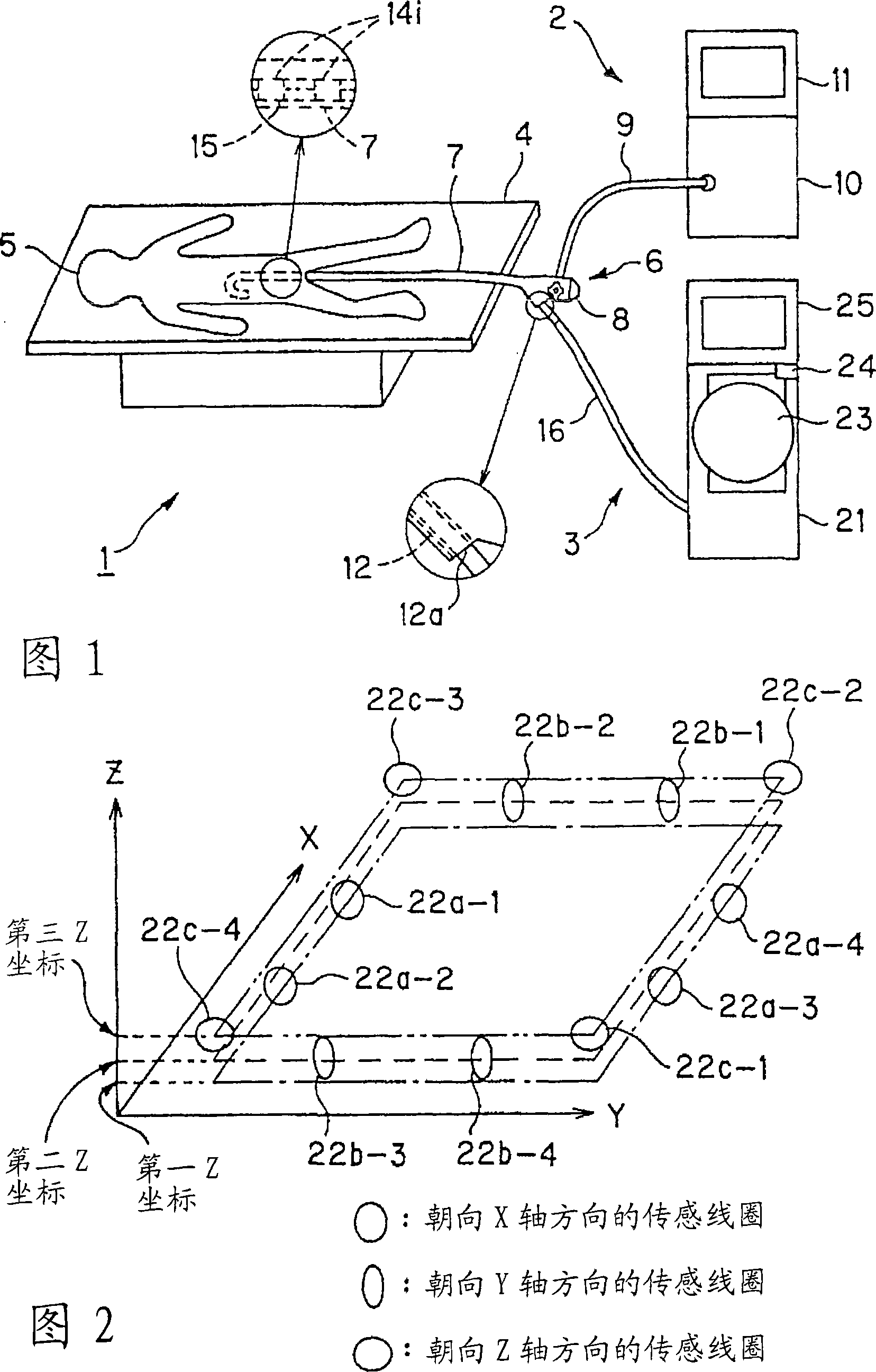
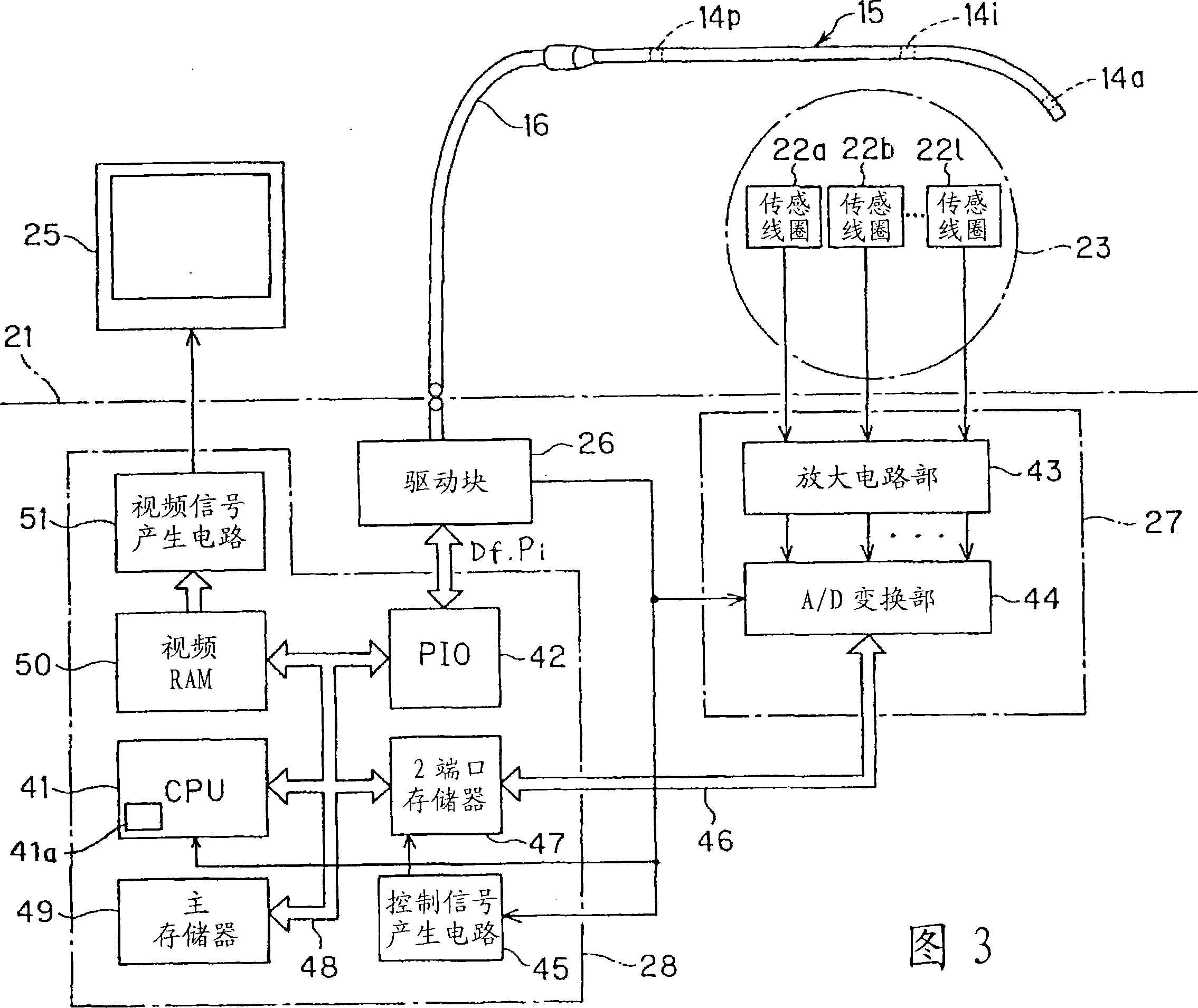
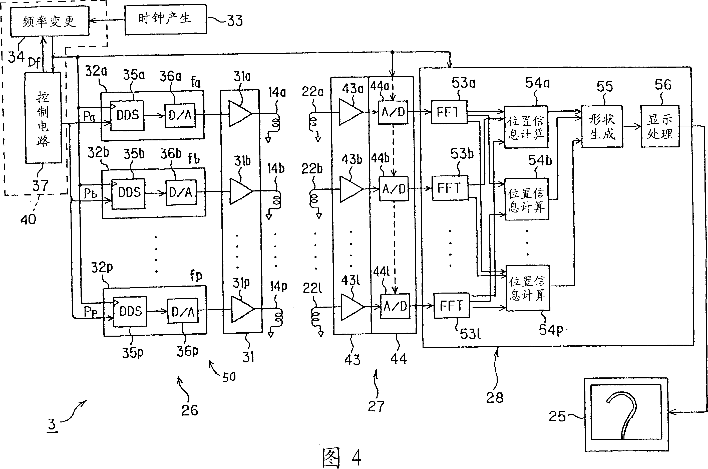
[0024] Embodiment 1 of the present invention will be described with reference to FIGS. 1 to 5 .
[0025] As shown in FIG. 1 , an endoscope system 1 has: an endoscope device 2 that performs endoscopic inspection; and an endoscope shape detection device 3 of Embodiment 1 that is used to assist endoscopic inspection, This endoscope shape detection device 3 is used as an insertion assisting means when inserting an insertion portion 7 of an electronic endoscope 6 into a body cavity of a patient 5 lying on a bed 4 for endoscopic inspection.
[0026] The electronic endoscope 6 is provided with an operation part 8 provided with a bending operation knob at the rear end of the flexible and elongated insertion part 7, and a universal cord 9 is extended from the operation part 8. Connect with video processor (or video imaging system) 10.
[0027] This electronic endoscope 6 is inserted with a light guide that transmits the illumination light from the light source unit in the video proces...
Embodiment 2
[0083] Next, Embodiment 2 of the present invention will be described with reference to FIG. 6 and FIG. 7 . FIG. 6 shows the configuration of an endoscope shape detection device 3B according to the second embodiment.
[0084] The endoscope shape detection device 3B detects the position of the source coil 14i with high accuracy by using synchronous detection.
[0085] The endoscope shape detection device 3B shown in FIG. 6 has a drive block 26B, a detection block 27B, a main processor 28B, and a liquid crystal monitor 25 .
[0086] The drive block 26B of this embodiment is constituted as follows: in the drive block 26 shown in FIG. The signal passes through a multiplexer (multiplexer) 61 to sequentially drive, for example, 16 source coils 14i, that is, to drive by time division. According to a switching control signal from the control circuit 37, the multiplexers 61 are sequentially switched at a predetermined cycle.
[0087] In addition, the detection block 27B of this embod...
Embodiment 3
[0111] Next, Embodiment 3 of the present invention will be described with reference to FIG. 8 . FIG. 8 shows the configurations of the drive block 26B, the detection block 27, and the main processor 28C of the endoscope shape detection device 3C according to the third embodiment.
[0112] This endoscope shape detection device 3C detects the position of the source coil 14i with high accuracy by using synchronous detection as in the second embodiment.
[0113] In this embodiment, the function of the synchronous detection circuit 62j in the second embodiment is realized by the main processor 28C.
[0114] The endoscope shape detection device 3C shown in FIG. 8 has a drive block 26B, a detection block 27 , a main processor 28C, and a liquid crystal monitor 25 .
[0115] In this embodiment, the function of the synchronous detection circuit 62j in the second embodiment is realized by software in the main processor 28C.
[0116] Other structures are the same as in Embodiment 2.
...
PUM
 Abstract
Description
Claims
Application Information
 - R&D
- Intellectual Property
- Life Sciences
- Materials
- Tech Scout
- Unparalleled Data Quality
- Higher Quality Content
- 60% Fewer Hallucinations
Browse by: Latest US Patents, China's latest patents, Technical Efficacy Thesaurus, Application Domain, Technology Topic, Popular Technical Reports.
© 2025 PatSnap. All rights reserved.Legal|Privacy policy|Modern Slavery Act Transparency Statement|Sitemap|About US| Contact US: help@patsnap.com