
Drop base ring clamping contour for air tubular bellow pneumatic springs

An air spring and hose type technology, which is applied in the direction of springs, spring/shock absorbers, gas shock absorbers, etc., can solve the problems of unsatisfied tensile strength and tensile strength, meet high sealing requirements, improve resistance breaking strength and low cost

Inactive Publication Date: 2007-10-31
CONTITECH LUFTFEDERSYST
View PDF1 Cites 1 Cited by
  • Summary
  • Abstract
  • Description
  • Claims
  • Application Information

AI Technical Summary

Problems solved by technology

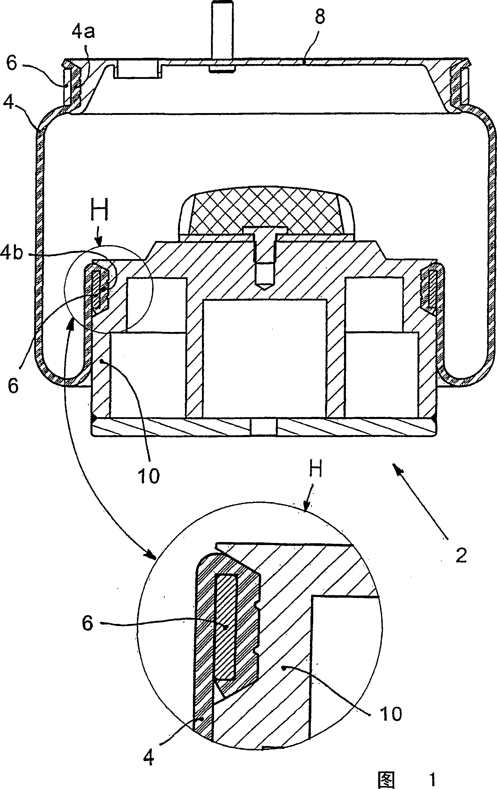
Therefore, on the structure shown in FIG. 1, the desired tensile strength, in particular, the magnitude of the tensile strength that should be required on commercial vehicles does not seem to be satisfied.

Method used


Image

  • Drop base ring clamping contour for air tubular bellow pneumatic springs
  • Drop base ring clamping contour for air tubular bellow pneumatic springs
  • Drop base ring clamping contour for air tubular bellow pneumatic springs

Examples


Embodiment Construction

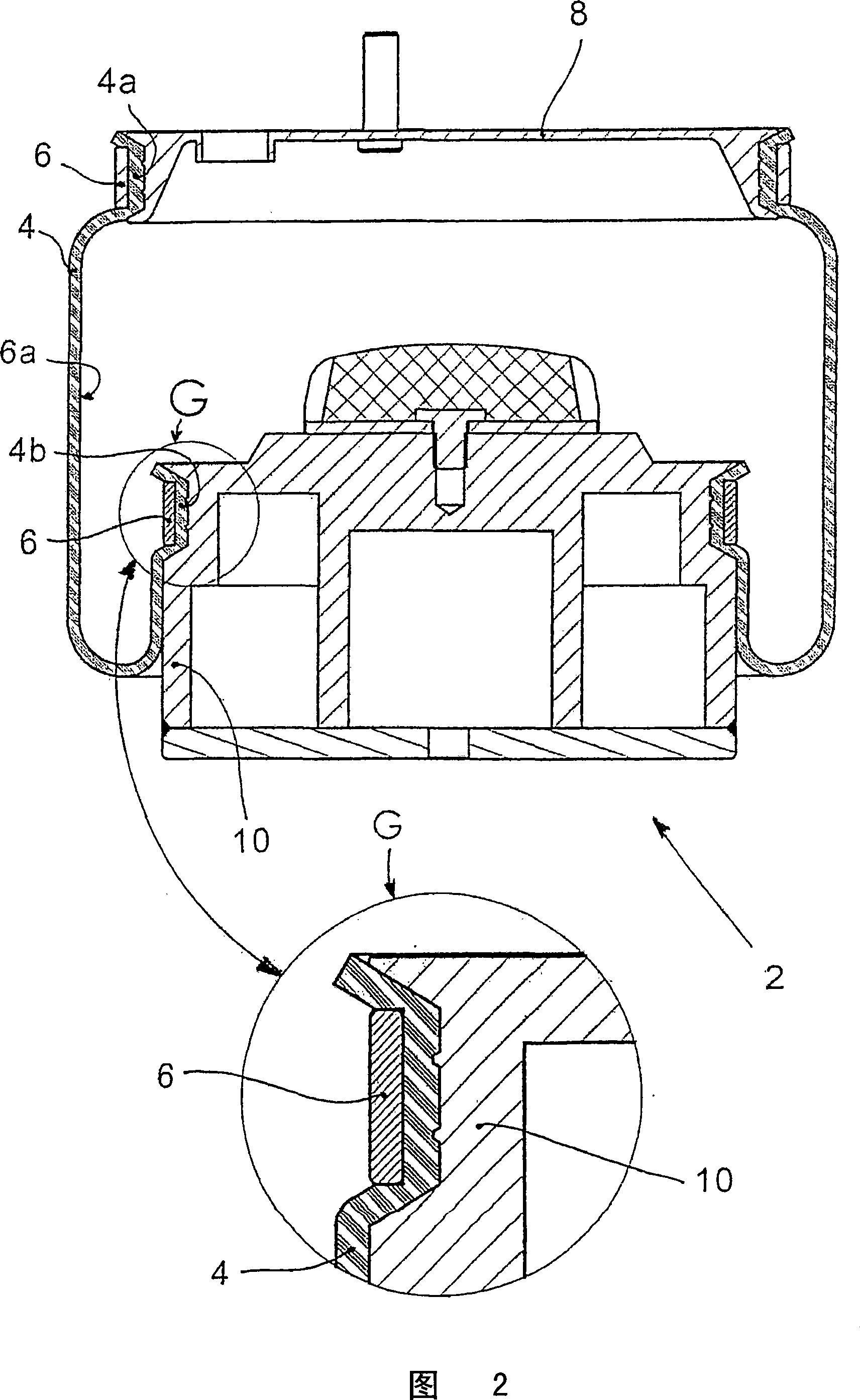
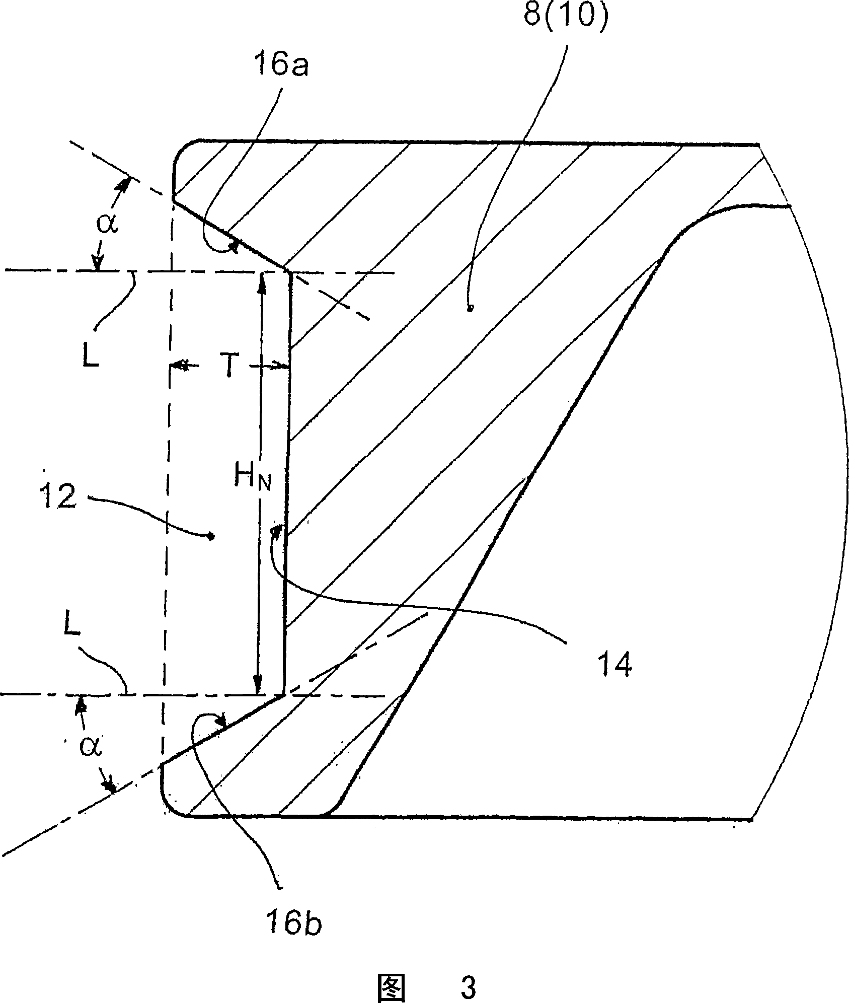
[0023] The air spring 2 shown in FIGS. 1 and 2 essentially comprises a tubular rolling film 4 , whose end sections 4 a , 4 b are positively fitted, tensile-resistant and gas-tight on the corresponding connecting piece 8 , 10 . The "upper" connecting part 8 is correspondingly an air spring cover, and the "lower" connecting part 10 is correspondingly an unwinding piston. The connecting parts 8 , 10 each have a specially formed groove 12 for fastening the tubular rolling foil ends 4 a , 4 b . An end section 4 a or 4 b of a tubular rolling film 4 is inserted into these grooves 12 and clamped in each case by means of a clamping ring 6 . As a result of the plastic deformation of the clamping ring 6 , the tubular rolling film 4 is pressed into the groove 12 formed as a “lower profile” which runs around in the respective connecting piece 8 and / or 10 .

[0024] The air spring 2 according to FIG. 2 differs from the air spring 2 shown in FIG. 1 in that here the tubular rolling film 4 is...


PUM


Abstract

In a driving unit (e.g., a gate driving unit) and a flat panel display apparatus having the driving unit, a circuit portion of the driving unit includes a plurality of driving stages cascade-connected to one another and outputs a (gate) driver signal (a plurality of gate-driving signals) based on a plurality of control signals. The line portion comprises a first signal line and a second signal line, each of which transmits control signals from the outside, and a first connection line connecting the first signal line to the driving stages, and a second connection line connecting the second signal line to the driving stages. The second signal line is positioned at a different (metallization) layer from the first signal line and the first and second connection lines. Therefore, malfunctioning of the driving unit caused by corrosion may be prevented.

Description

technical field [0001] The invention relates to a rolling membrane-air spring, and more precisely to the fastening of a hose-type rolling membrane (Schlauchrollbalg) on ​​a connecting part (air spring cover and / or unwinding piston (Abrollkolben)), said connecting parts corresponding The form-fitting connection is tensile and gas-tight on the end face which is placed on the foil. Background technique [0002] European patent application 0 319 448 A2 relates to fastening an air spring membrane at the ends to corresponding connecting pieces. Figure 4 in this patent application shows all the main details: For securing the hose-type rolled film-end section, the fastener has a groove. This groove has a base which can be provided with a circumferential groove 24 . The side walls of the groove are partially arched and partially conically inclined at different angles α and β. Clamping takes place over the entire height of the clamping ring by the compression of the film. Since th...

Claims


Application Information

Patent Timeline
Patent Type & Authority Applications(China)
IPC IPC(8): F16F9/04F16F9/084
CPCF16F9/0463
Inventor C·本克P·策尔尼H·加文斯基
Owner CONTITECH LUFTFEDERSYST
Learn More