
A space liquid sealing lubricating device

A liquid sealing and lubricating device technology, applied in bearing components, shafts and bearings, mechanical equipment, etc., can solve problems such as non-normal operation, complex structure, oil pump damage, etc., to reduce the leakage of lubricating oil and inhibit the effect of escaping

Inactive Publication Date: 2015-11-04
BEIHANG UNIV
View PDF5 Cites 0 Cited by
  • Summary
  • Abstract
  • Description
  • Claims
  • Application Information

AI Technical Summary

Problems solved by technology

In addition, the high-altitude microgravity environment also makes the traditional ground liquid lubrication system unable to work normally. For example, the lubricating oil floats somewhere in the oil tank in a spherical shape, causing the oil pump to work in a state of oil shortage and damage; and the evaporation and creep of the lubricating oil It is also the main problem faced by space lubrication, so a reliable sealing lubrication device must be designed
At present, the liquid lubrication of space mechanical equipment is mainly composed of a porous cage immersed in lubricating oil and an auxiliary oil reservoir, and then the lubricating oil is replenished from the auxiliary oil reservoir to the surface to be lubricated through capillary effect, heating and vibration, not only The quality is large and the structure is complex, and its sealing device is mainly an oil-resistant rubber sealing ring

Method used


Image

  • A space liquid sealing lubricating device
  • A space liquid sealing lubricating device
  • A space liquid sealing lubricating device

Examples


Embodiment Construction

[0026] The present invention will be described in further detail below in conjunction with the accompanying drawings and specific embodiments.

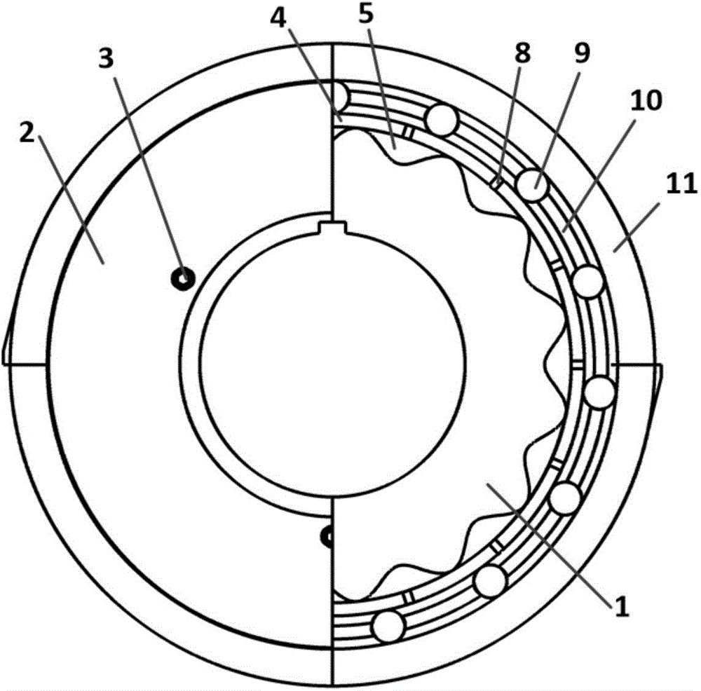
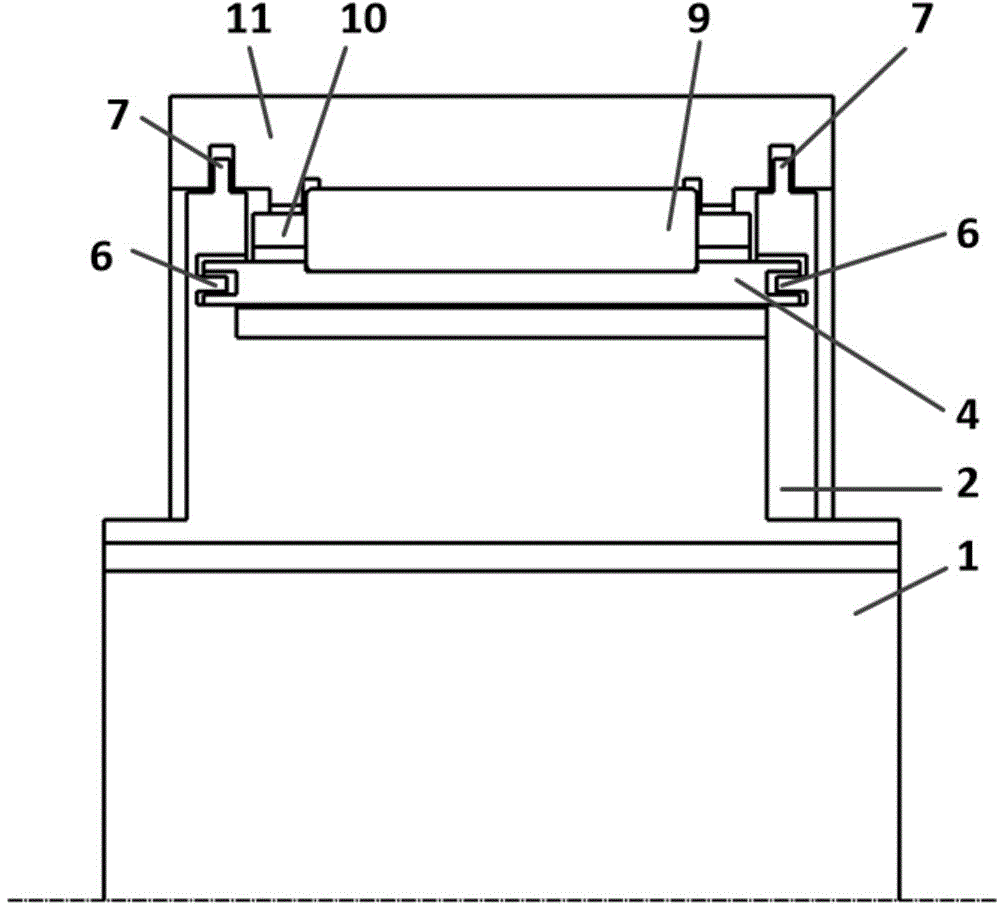
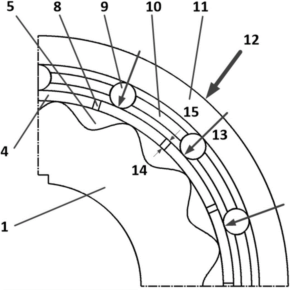
[0027] Such as Figure 1.1 and Figure 1.2 Shown is the structural representation of the present invention. A space liquid sealing lubricating device of the present invention is composed of a support body 1, an inner baffle plate 2, a set screw 3, an elastic body 4, an oil storage chamber 5, a first group of labyrinth seals 6, a second group of labyrinth seals 7, and an oil hole 8. Rolling body 9, cage 10 and bearing outer ring 11 are composed of several parts. The positional connection relationship between them is: the support body 1 is located inside the device, the inner baffle plate 2 is located on the right side of the support body 1, its left end surface is in contact with the support body 1, and is fixedly connected with the support body 1 by the set screw 3, The elastic body 4 is located between the supporting body 1 and the...


PUM


Abstract

The invention discloses a space liquid sealing lubricating device which comprises a supporting body, an inner baffle, a fastening screw, an elastomer, an oil storage cavity, a first group of labyrinth seals, a second group of labyrinth seals, oil holes, rolling bodies, a retaining frame and a bearing outer ring, wherein the supporting body is arranged in the device; the inner baffle is arranged on one side of the supporting body and is fixedly connected with the supporting body; the elastomer is arranged between the supporting body and the rolling bodies; the inner circumferential surface of the elastomer, the inner end surface of the inner baffle and the adjacent surfaces of the supporting body jointly form the oil storage cavity; double bosses on the edge of the elastomer, double grooves in the inner side surface of the inner baffle and double grooves in the inner side surface of a disk of the supporting body form the first group of labyrinth seals; grooves in the left and right ends of the bearing outer ring, bosses on the outer circumferential surface of the inner baffle and bosses on the outer circumferential surface of the disk of the supporting body form the second group of labyrinth seals; the rolling bodies are arranged outside the elastomer and are circumferentially distributed uniformly; the retaining frame is connected with the rolling bodies and is arranged between the elastomer and the bearing outer ring; the inner circumferential surface of the bearing outer ring makes contact with the rolling bodies.

Description

technical field [0001] The invention relates to a space liquid sealing lubrication device, which belongs to the technical field of space liquid sealing lubrication. Background technique [0002] Space vehicles usually work at altitudes above 500km, and their ambient pressure is usually 1.33×10 -8 High vacuum above Pa. In a high vacuum environment, two smooth metal surfaces in contact will produce cold and friction welding, which is fatal to moving parts. Therefore, the high vacuum environment has special requirements for lubrication. In addition, the high-altitude microgravity environment also makes the traditional ground liquid lubrication system unable to work normally. For example, the lubricating oil floats somewhere in the oil tank in a spherical shape, causing the oil pump to work in a state of oil shortage and damage; and the evaporation and creep of the lubricating oil It is also the main problem faced by space lubrication, so a reliable sealing lubrication device...

Claims


Application Information

Patent Timeline
Patent Type & Authority Patents(China)
IPC IPC(8): F16C33/66F16C33/80
Inventor 姬芬竹杜发荣郭雨琛聂磊谷可帅
Owner BEIHANG UNIV
Learn More