Linear guide device

A technology of guiding devices and guide rails, which is applied in the direction of linear motion bearings, bearings, bearing components, etc., and can solve problems such as poor assembly of sliders

Active Publication Date: 2010-05-19
NSK LTD
View PDF6 Cites 0 Cited by
  • Summary
  • Abstract
  • Description
  • Claims
  • Application Information

AI Technical Summary

Problems solved by technology

Therefore, it is necessary to assemble the rolling element retaining member integrated with the return guide to the slider body before inserting the rolling element return passage constituting member guiding the spacer holding belt, which is used for The distance between the rolling elements is maintained so that the rolling elements do not interfere with each other, so there is also a problem that the assembly of the slider is deteriorated.

Method used


Image

  • Linear guide device
  • Linear guide device
  • Linear guide device

Examples


no. 1 approach

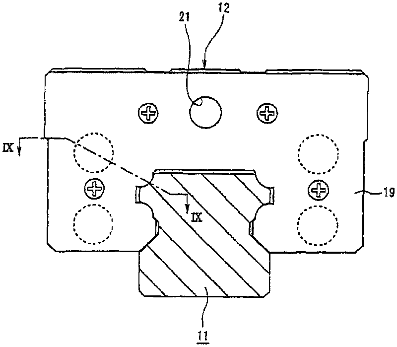
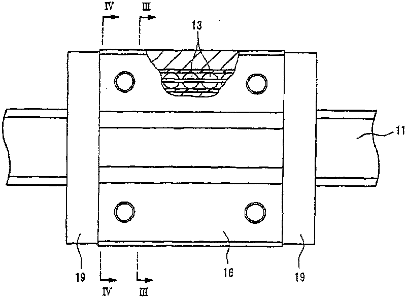
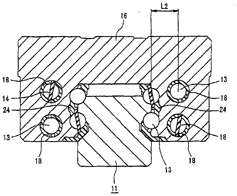
[0040] exist figure 1 with figure 2 Among them, the linear guide device of the first embodiment of the present invention is composed of the following parts: a guide rail 11 formed in a straight line; a slider 12 that relatively moves in the length direction of the guide rail 11; a freely rolling assembly on the slider 12 A plurality of balls 13 as rolling bodies inside; and four spacing maintaining strips 14 (refer to image 3 with Figure 4 ).

[0041] The guide rail 11 is made of metal materials such as steel, and has rolling grooves 15 on the side of the rail L1 、15 L2 、15 R1 、15 R2 (refer to Figure 5 ). These track side rolling element rolling grooves 15 L1 ~15 R2 The rolling grooves of the two track side rolling elements in the 15 L1 、15 R1The intersection of the upper surface part 111 of the guide rail 11 and the left and right side parts 112, 112 is formed along the length direction of the guide rail 11, and the remaining two rail side rolling element roll...


PUM


Abstract

A linear guide device, wherein a rolling element cage (24) holding balls interposed between a rail side rolling element rolling groove and a slider side rolling element rolling groove comprises two plate parts (244) formed of a synthetic resin material and facing each other on both sides of the slider body of a slider. The rolling element cage (24) comprises a positioning part in contact with theinner surface of the slider body and is positioned on the slider body by the positioning part.

Description

technical field [0001] The present invention relates to a linear motion guide device for guiding an object in a reciprocating linear motion along its moving direction. Background technique [0002] A linear motion guide device that guides an object that performs reciprocating linear motion along its moving direction generally includes: a guide rail formed in a straight line; a slider that relatively moves in the length direction of the guide rail; and a slider that is assembled in the slider and Multiple rolling bodies that can roll freely. In addition, the slider includes: a slider main body having a plurality of slider-side rolling-element rolling grooves respectively opposed to a plurality of rail-side rolling-element rolling grooves formed on the guide rail; a pair of end caps mounted on the slider On one end and the other end of the main body; a plurality of return guides forming a turning path between the returning guides and the end cover, the turning paths are conne...

Claims


Application Information

Patent Timeline
Patent Type & Authority Patents(China)
IPC IPC(8): F16C29/06F16C33/38F16C33/37
Inventor 山口宏树仓知信秀水村美典
Owner NSK LTD
Why Eureka
Try Eureka