Diffusion optical sheet, deflection optical sheet, and transmission screen

A technology of optical diffusion and optical deflection, applied in optics, optical components, projectors with built-in screens/external screens, etc., can solve the problems of glass fragments flying, fragments flying out, etc., and achieve the effect of suppressing warpage

Inactive Publication Date: 2007-11-07
DAI NIPPON PRINTING CO LTD
View PDF4 Cites 11 Cited by
  • Summary
  • Abstract
  • Description
  • Claims
  • Application Information

AI Technical Summary

Problems solved by technology

However, in this transmissive screen, the front surface (the surface closest to the observer) on the exit side of the screen is a glass substrate, so there is a problem that the glass shatters when the glass substrate is damaged due to an accident or the like. will scatter out
However, since the outermost surface of the screen disclosed in this document is a glass substrate, there is a problem that fragments are scattered when the glass substrate is broken or the like.

Method used


Image

  • Diffusion optical sheet, deflection optical sheet, and transmission screen
  • Diffusion optical sheet, deflection optical sheet, and transmission screen
  • Diffusion optical sheet, deflection optical sheet, and transmission screen

Examples


Embodiment 1

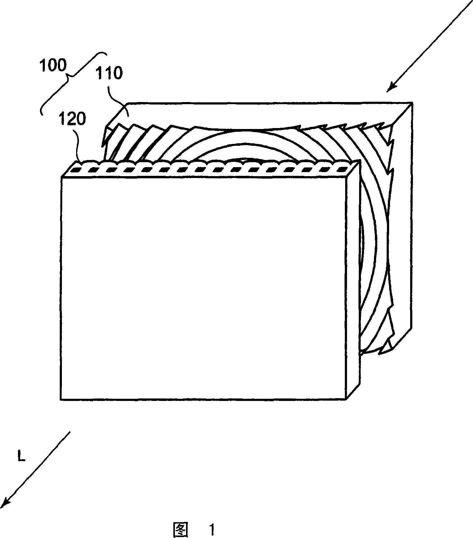
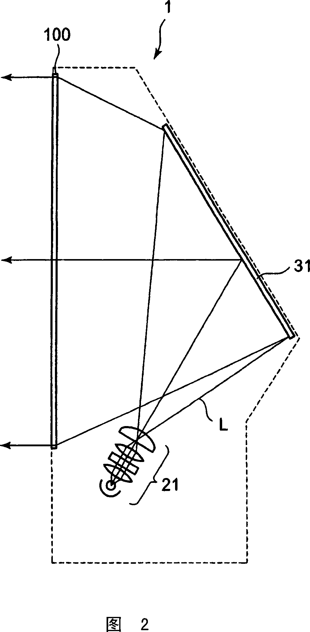
[0061] FIG. 1 is a diagram showing a transmissive screen according to Embodiment 1 of the present invention. FIG. 2 is a cross-sectional view of a rear projection television using the transmissive screen of Embodiment 1. FIG.

[0062] As shown in FIG. 1 , the transmissive screen 100 of Embodiment 1 includes an optical deflection sheet provided on the incident side (light source side) of the video light L and an optical diffusion sheet provided on the outgoing side of the video light L (observation surface side). ; Arranged on the imaging plane of the image light L. In this transmissive screen, the optical diffusion sheet is formed as a lenticular sheet having lenticular lenses. On the other hand, the optical deflection sheet is formed as a Fresnel lens sheet having a Fresnel lens.

[0063] As shown in FIG. 2 , the rear projection TV 1 is provided with a transmissive screen 100, a light source unit 21 disposed on the side (hereinafter also referred to as the incident side) of...

Embodiment 2

[0103] Fig. 11 is a diagram showing a transmissive screen according to Embodiment 2 of the present invention. As shown in FIG. 11 , the transmissive screen 400 of the second embodiment includes an optical deflection sheet provided on the incident side of the video light L and an optical diffusion sheet 420 provided on the outgoing side of the video light L. In addition, the transmissive screen 400 of the second embodiment is applied to the rear projection television 1 shown in FIG. 2 in the same manner as the transmissive screen 100 described in the first embodiment.

[0104] In this transmissive screen, the optical deflection sheet is formed as a Fresnel lens sheet having a Fresnel lens as in the first embodiment. On the other hand, the optical diffusion sheet 420 is composed of a sheet-shaped member different from that of the first embodiment, as described later.

[0105] Fig. 12 is a schematic view showing the layer structure of a transmissive screen of Example 2 using the...

Embodiment 3

[0128] Fig. 15 is a diagram showing a transmissive screen according to Embodiment 3 of the present invention. Fig. 16 is a cross-sectional view of a rear projection television using the transmissive screen of the third embodiment.

[0129] As shown in FIG. 15 , the transmissive screen 200 of Embodiment 3 includes an optical deflection film provided on the incident side of the video light L (on the light source side) and an optical diffuser provided on the outgoing side of the video light L (on the viewing surface side). piece. In addition, a set of transmissive screens is formed by combining the optical deflection sheet and the optical diffusion sheet, which are used in the rear projection TV 2 shown in FIG. 16 .

[0130] In this transmissive screen, the optical diffusion sheet is formed as a lenticular lens sheet having the lenticular lenses used in Example 1. On the other hand, as will be described later, the optical deflection sheet is formed as a prism sheet including a ...


PUM


Abstract

A diffusion optical sheet in which the image quality can be prevented from deteriorating because of warp caused by environmental variation, and fragments can be prevented from scattering even if a substrate is damaged due to failure or the like. The diffusion optical sheet (120) is employed in a transmission screen where video light projected from the incoming side exits to the outgoing side. The diffusion optical sheet (120) comprises a high-rigidity light-transmitting substrate layer (121) and a plurality of layers formed on the high-rigidity substrate layer. The plurality of layers include at least a pair of layers arranged on both sides of the high-rigidity substrate layer and preventing scattering thereof. At least any one of the two or more layers has a diffusion optical element for diffusing video light.

Description

technical field [0001] The present invention relates to an optical diffusion sheet and an optical deflection sheet used in a transmissive screen that emits image light projected from a light source toward the exit side, and a transmission screen using at least any one of the optical diffusion sheet and the optical deflection sheet. type screen. Background technique [0002] In a rear projection display device projecting video light from the back of the screen for display, a transmissive screen is used as a screen for projecting and enlarging video light for display. Generally speaking, this transmissive screen uses an optical deflection sheet (such as a Fresnel lens sheet: Fresnellens sheet) and an optical diffusion sheet (such as a lenticular lens sheet: lenticular lenssheet) in combination, wherein the former makes the image light projected by the light source Refracts light roughly parallel to the side of the viewing surface that diffuses the image light. [0003] Conve...

Claims


Application Information

Patent Timeline
Patent Type & Authority Applications(China)
IPC IPC(8): G03B21/62G03B21/10G02B3/08G02B3/00G03B21/625
Inventor 儿玉大二郎柏木刚加藤圭
Owner DAI NIPPON PRINTING CO LTD
Why Eureka
Try Eureka