Foot massager
A foot and support technology, applied in vibration massage, kneading massage equipment, massage auxiliary products, etc., can solve the problems of poor blood circulation and insufficient massage effect.
- Summary
- Abstract
- Description
- Claims
- Application Information
AI Technical Summary
Problems solved by technology
Method used
Image
Examples
Embodiment 1
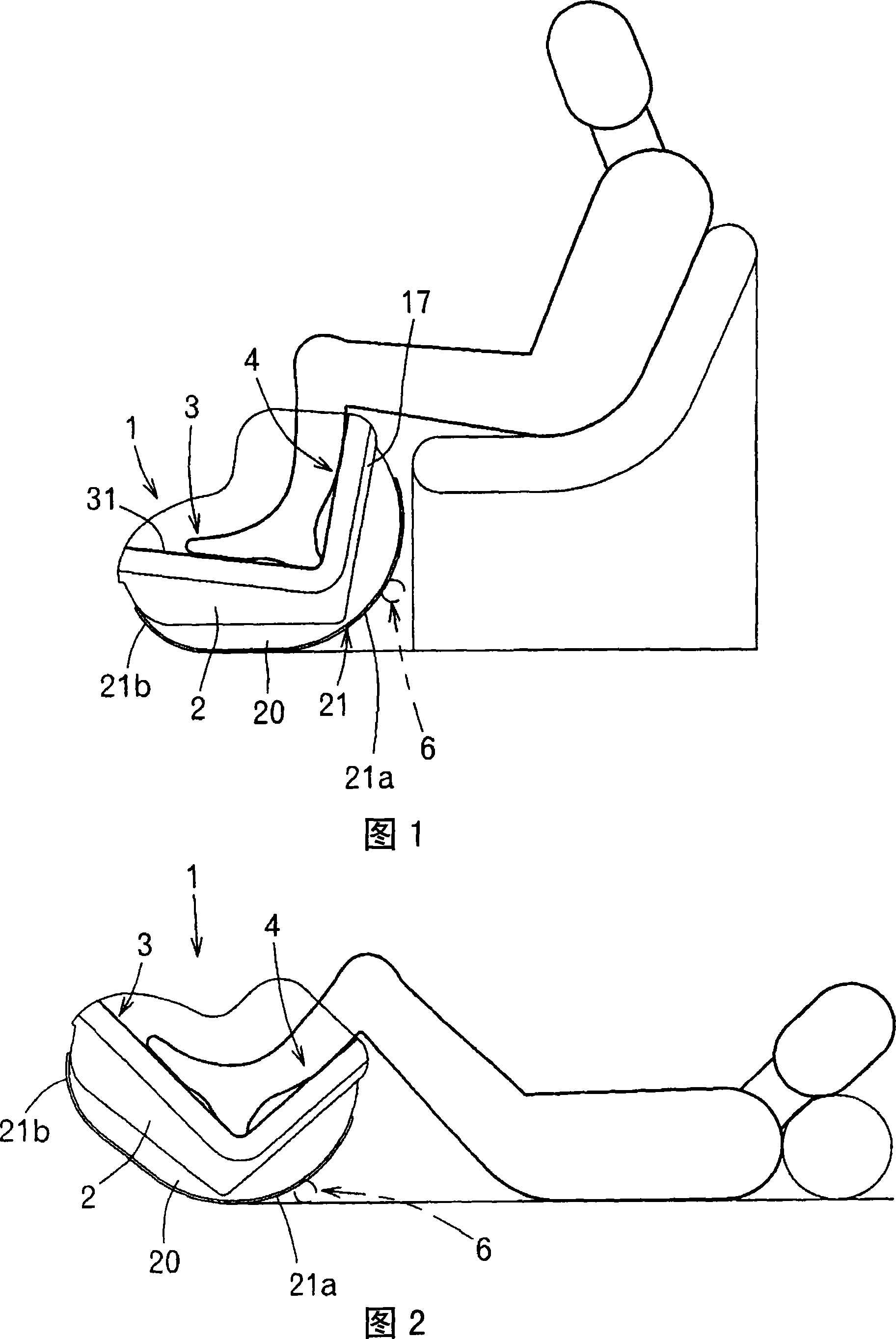
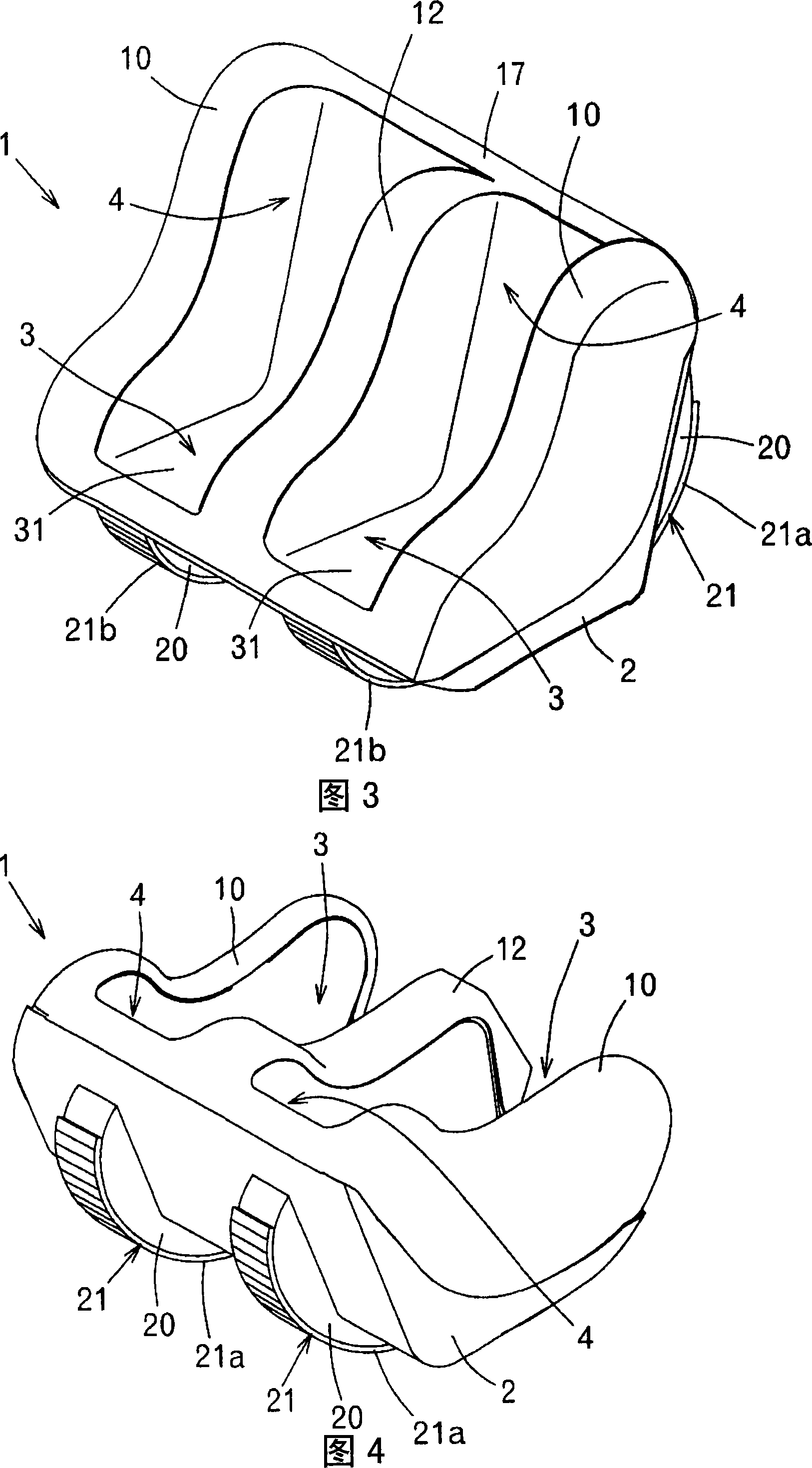
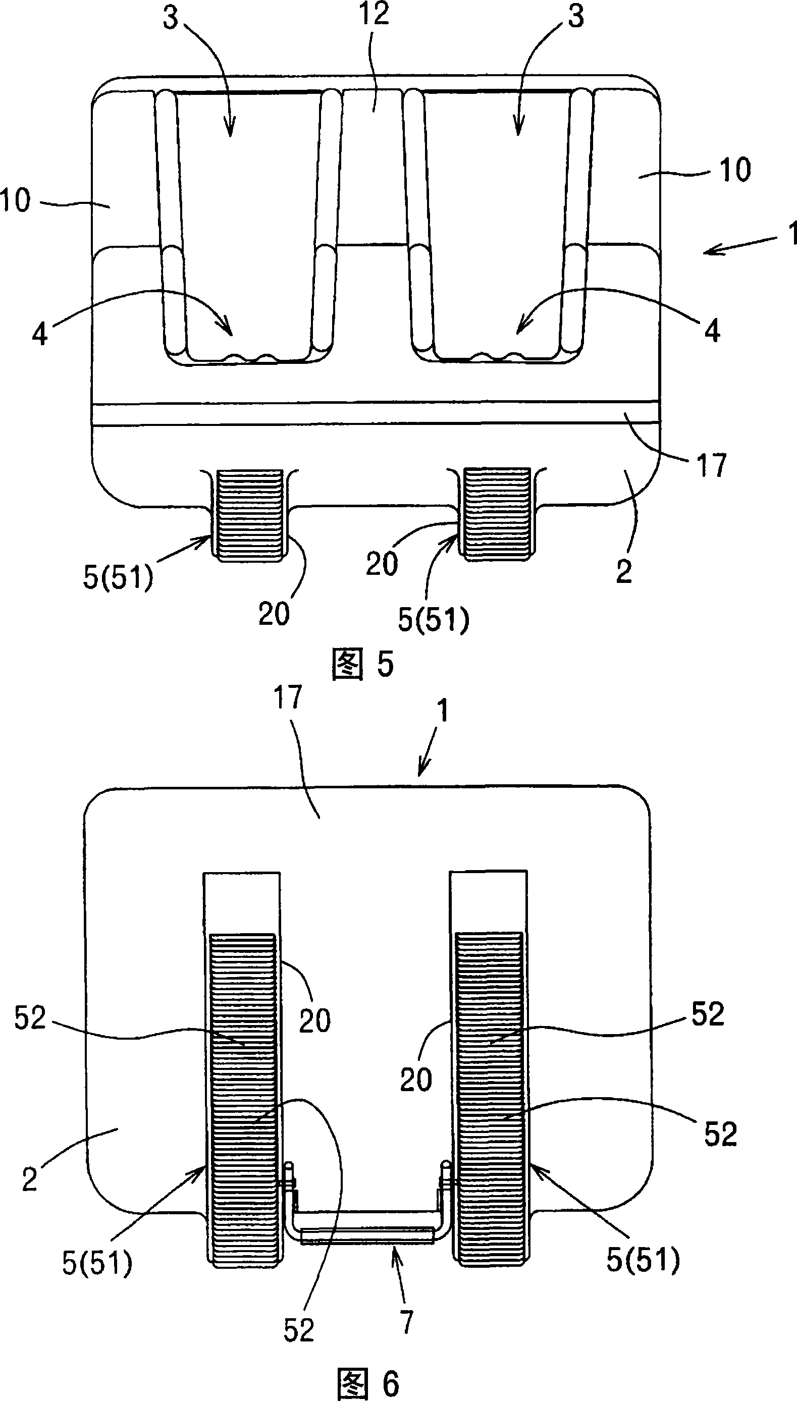
[0035] Fig. 1 and Fig. 2 are explanatory diagrams of the use state of the foot massager 1 of the present invention, Fig. 3 is a perspective view of the massager 1 when viewed from the front side, Fig. 4 is a perspective view when viewed from the back side, and Fig. 5 is The top view of massage machine 1, Fig. 6 is a rear view.
[0036] As shown in the figure, on the main body casing 2 of the massage machine 1, two concave support parts 3, 3 for independently accommodating the toes of the feet of the person to be treated, and two leg support parts 4 for accommodating the calf are formed. 4, wherein the two leg support parts 4, 4 are formed continuously with the rear side of the concave support part 3, 3 and facing upward.
[0037] As shown in FIG. 1 , hereinafter, the orientation of the toes of a person sitting on a chair when the toes are accommodated in the concave support portion 3 and the calf is accommodated in the leg support portion 4 is referred to as “front”.
[0038]...
Embodiment 2
[0072] As shown in FIG. 11 , in the massage machine 1 , a stopper 6 for restricting the reclining angle of the massage machine 1 is provided on the back side of the leg support portion 4 .
[0073] The stopper 6 is formed by covering a cylindrical elastic cover 62 on a circular shaft 61 provided to connect the legs 20 , 20 .
[0074] As shown in FIG. 2 , if the leg support portion 4 is tilted backward by about 45° from a substantially vertical state relative to the ground, the stopper 6 will contact the ground to prevent further backward tilting.
[0075] The stopper 6 is simultaneously used as a handle for lifting the massage machine 1 .
[0076] The following situation can be avoided by the stopper 6: the massage machine 1 is excessively tilted backward, and a gap is generated between the calf and the calf massage mechanism 13, resulting in that the calf cannot receive massage.
[0077] The stopper 6 is covered by the elastic cylinder 62, so the impact when the stopper 6 co...
Embodiment 3
[0080] 13 and 16 illustrate that the massage machine 1 is equipped with a safety frame 7 that prevents the massage machine 1 from tilting backward.
[0081] The safety frame 7 rotates around the fulcrum 71 erected between the feet 20, 20, and can enter and exit from the feet 20, 20 to the outside. When using the massage machine 1, as shown in FIG. 14, it is folded and stored Between the feet 20 , 20 there is thus no hindrance to the swiveling of the massage machine 1 .
[0082] As shown by the arrows in FIG. 13 , when the safety frame 7 is pulled out, backward tilting from the state where the flat surfaces 22 of the legs 20 and 20 are in contact with the ground is prevented.
[0083] It is possible to prevent the massage machine 1 from falling due to the backward tilting of the massage machine 1 when riding on the concave support portion 3 of the massage machine 1 inadvertently.
[0084] It is also possible to configure a safety frame (not shown) on the front side of the bott...
PUM
 Abstract
Description
Claims
Application Information
 - R&D
- Intellectual Property
- Life Sciences
- Materials
- Tech Scout
- Unparalleled Data Quality
- Higher Quality Content
- 60% Fewer Hallucinations
Browse by: Latest US Patents, China's latest patents, Technical Efficacy Thesaurus, Application Domain, Technology Topic, Popular Technical Reports.
© 2025 PatSnap. All rights reserved.Legal|Privacy policy|Modern Slavery Act Transparency Statement|Sitemap|About US| Contact US: help@patsnap.com


