

Sealed rolling rotor type compressor bearing structure
A rolling rotor type compressor technology, applied in the field of compressor bearings, can solve the problems of product reliability decline, easy to generate noise, easy to generate defects, etc., to achieve improved contact quality, improved performance, and reduced base area Effect
- Summary
- Abstract
- Description
- Claims
- Application Information
AI Technical Summary
Problems solved by technology
Method used
Image

Examples
Embodiment Construction
[0028] Below in conjunction with accompanying drawing and specific embodiment the present invention is described in further detail:
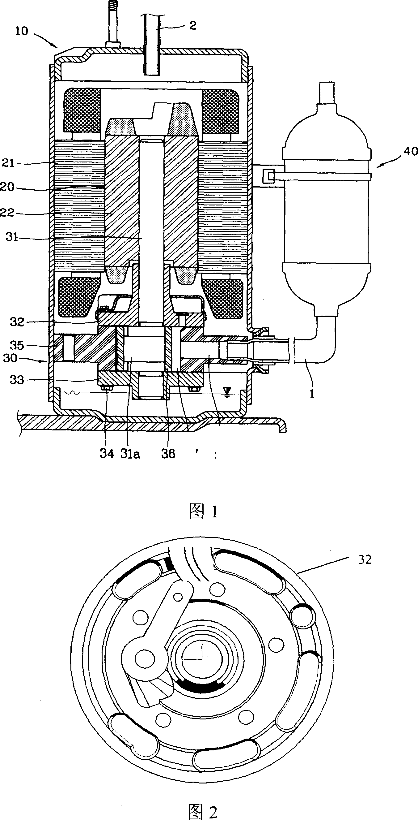
[0029] The overall structure of the hermetic rolling rotor compressor of the present invention is the same as that of the prior art, and the present invention will be described with reference to Fig. 1 .
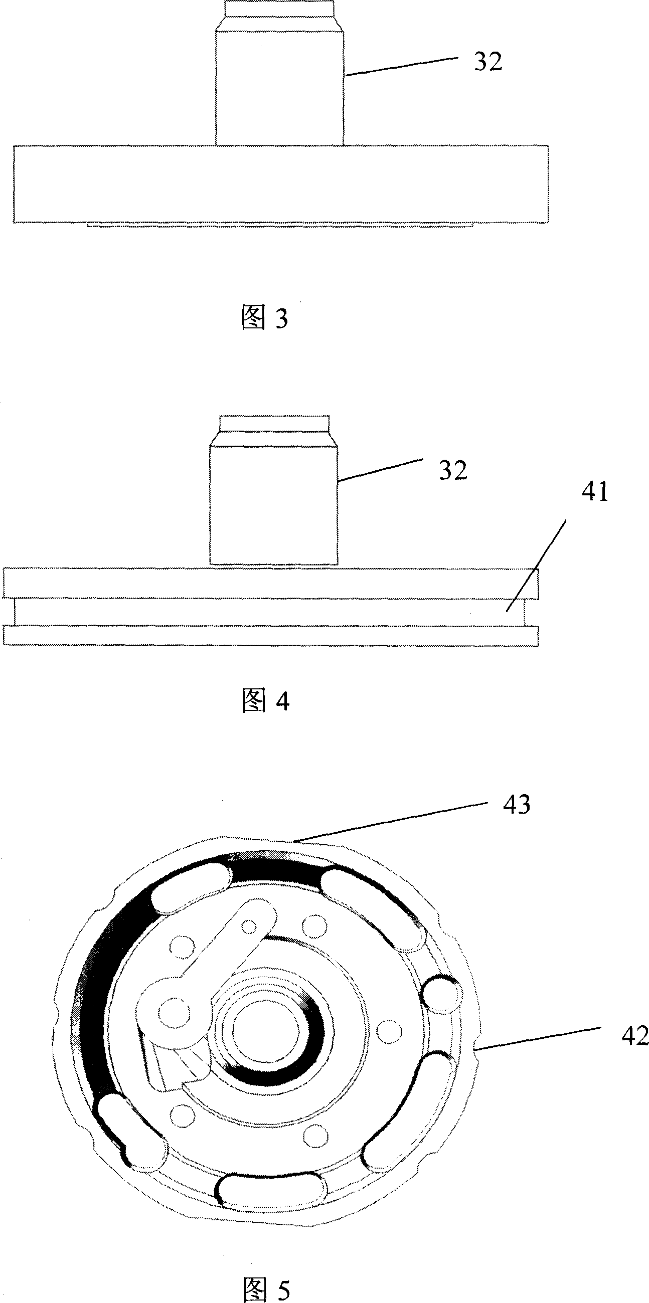
[0030] The sealed rolling rotor compressor of the present invention includes: a casing 30, the motor part 20 composed of a stator 21 and a rotor 22 inside the casing 30; the bottom of the compressor includes: a cylinder 35 with a certain space compression chamber inside; The inside of the rotor 22 is pressed into a fixed rotating shaft 31. There are upper bearings 32 and lower bearings 33 that can support the rotating shaft 31. The upper bearings 32 and the lower bearings 33 are fixed with fixed bearing screws 34. The top of the upper bearing 32 is provided with a lowering row. The muffler 38 of air noise; the inner surface of the roller ring ...
PUM
 Abstract
Description
Claims
Application Information