Conveyor

A technology for conveying devices and control devices, which is applied in the direction of conveyor objects, transportation and packaging, furnaces, etc., and can solve problems such as damage to substrate straightness, vibration, etc.

Active Publication Date: 2010-02-17
ULVAC INC
View PDF3 Cites 3 Cited by
  • Summary
  • Abstract
  • Description
  • Claims
  • Application Information

AI Technical Summary

Problems solved by technology

As shown in Japanese Patent Laid-Open No. 9-283588, by making the second pulley 107 ω 1 and ω 2 It is a shape of the same size, and can be operated at any position without conflicting with the control of the post

Method used


Image

  • Conveyor
  • Conveyor
  • Conveyor

Examples


no. 1 approach

[0174] Figure 9 The structure of the conveyance apparatus 110 which concerns on 1st Embodiment of this invention of a 2nd category is shown.

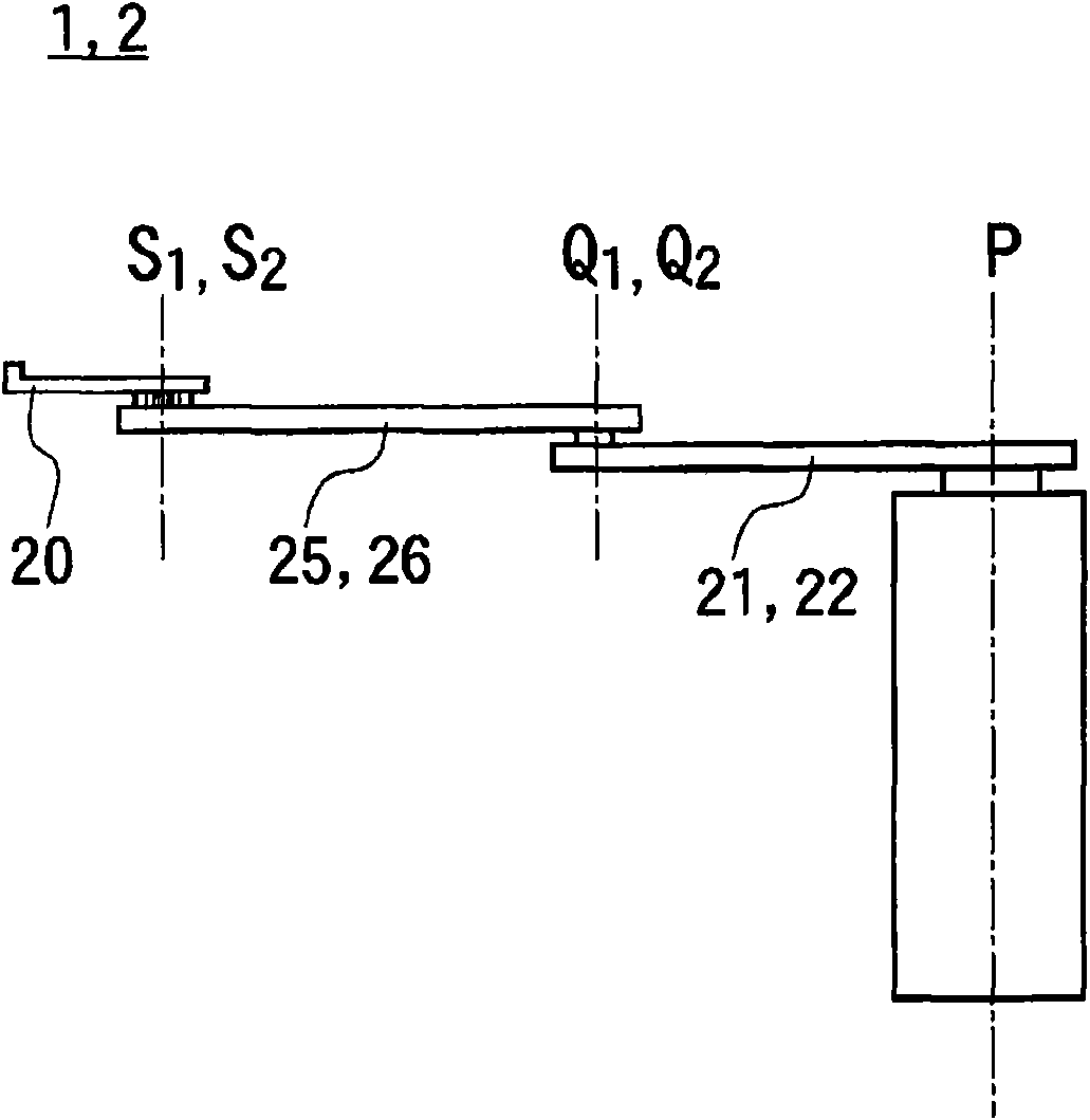
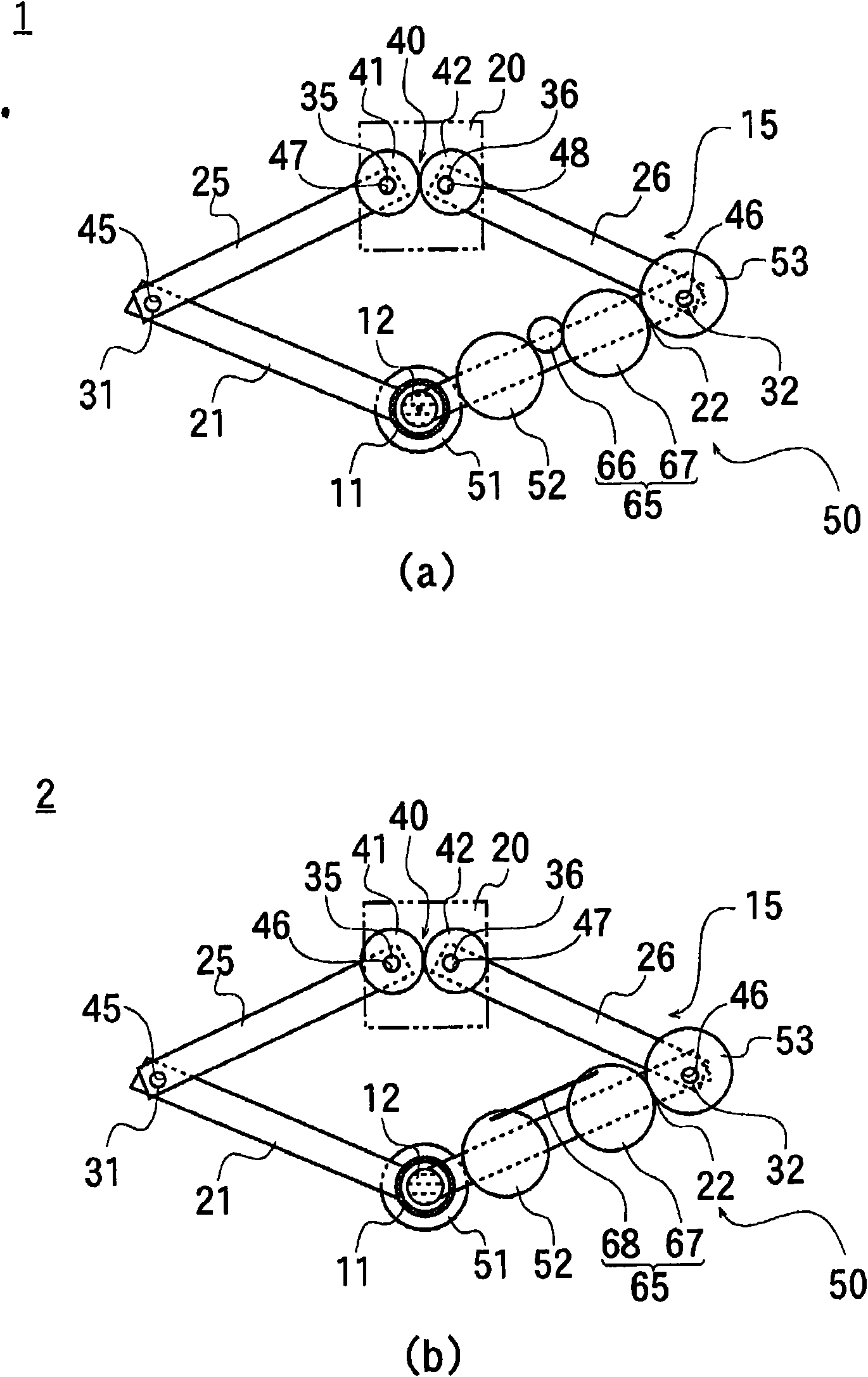
[0175] The transport device 110 of this embodiment includes: a base 103 having a pair of rotating shafts 101, 102 rotating in different directions; a pair of first arms 111, 112 connected to one end of the rotating shafts 101, 102; a pair of second arms 121 , 122 , one end of which is rotatably coupled to the respective other ends of these first arms 111 , 112 via arm coupling shafts 113 , 114 ; The substrate supports 104 to which the other ends are bonded.

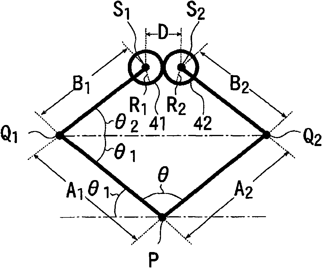
[0176] The first arms 111 , 112 and the second arms 121 , 122 have the same arm length, thereby forming a parallel link mechanism. Therefore, the angle ω formed by the first arms 111, 112 and the second arms 121, 122 is changed by rotating the rotation shafts 101, 102 in opposite directions, and the substrate support 104 moves vertically in the figure. Thereby, the substrate w ...


PUM


Abstract

A conveyor small in construction and less in environmental impact to working site. The conveyors (1, 2) in one aspect of this invention need less space to put them in, because of first and second rotating shafts (11, 12) lying in concentric relation with each other. A mechanism (50) to get out of the dead center is simple in construction and thin in thickness. A coupling at a hand part (20) can be made thin and, correspondingly, an opening of a gate valve to allow the hand part (20) passing through there can be also made small. The conveyor in another aspect is of the type in which two rotating shafts are spaced apart away from one another. With this version, a first arm installed on the rotating shaft can be sometimes different in length from a second arm lying between the first arm and a base supporter. Nevertheless, this conveyor, because the torque transfer of the mechanism (50) to get out of the dead center is released at anywhere else, won't result in working failure even if there is any difference in their length.

Description

technical field [0001] The present invention relates to the technical field of conveying devices. In particular, the first category of the present invention relates to a conveying device with a dead center escape mechanism, and the second category relates to carrying, for example, semiconductor substrates into or out of a vacuum processing chamber, etc. In the case of , it is a conveying device used to convey it to a predetermined position. Background technique [0002] <Background Art of First Category> [0003] A transfer device is used to transfer silicon wafers, glass substrates, etc., but the operating range is often limited by the usage environment. For example, when a transport device is operated in a special environment such as a vacuum in a semiconductor manufacturing device, it must be operated in a limited space inside the device, so the radius of gyration of the transport device must be small. [0004] In addition, in the case of conveying the object to b...

Claims


Application Information

Patent Timeline
IPC IPC(8): B25J9/06B25J9/04B65G49/07H01L21/677
Inventor 武者和博南展史吾乡健二浅石隆小池土志夫
Owner ULVAC INC
Why Eureka
Try Eureka