Ball bearing switch

A ball switch, ball technology, applied in electronic switches, electrical components, circuits, etc., can solve the problem of high probability of malfunction

Active Publication Date: 2007-11-28
ONCQUE CORP
View PDF1 Cites 4 Cited by
  • Summary
  • Abstract
  • Description
  • Claims
  • Application Information

AI Technical Summary

Problems solved by technology

[0012] Although the above-mentioned ball switch 10 can make the ball 15 roll by changing the angle to produce the effect of signal change, when the ball 15 rolls to the area near the second slot 117, it is easier to roll to block the receiving head 132. Position, that is, improperly located in the blocking position that blocks the direct communication path I, resulting in a place to be improved with a higher probability of malfunction

Method used


Image

  • Ball bearing switch
  • Ball bearing switch
  • Ball bearing switch

Examples


Embodiment Construction

[0034] The ball switch proposed according to the present invention will be described in detail below with reference to the accompanying drawings and preferred embodiments.

[0035] Before the present invention is described in detail, it should be noted that the relative positional terms used in the following descriptions, such as "first direction X" and "second direction Y" are based on the directions shown in each figure , and the first direction X and the second direction Y are perpendicular to each other, and similar elements are described with the same reference numerals.

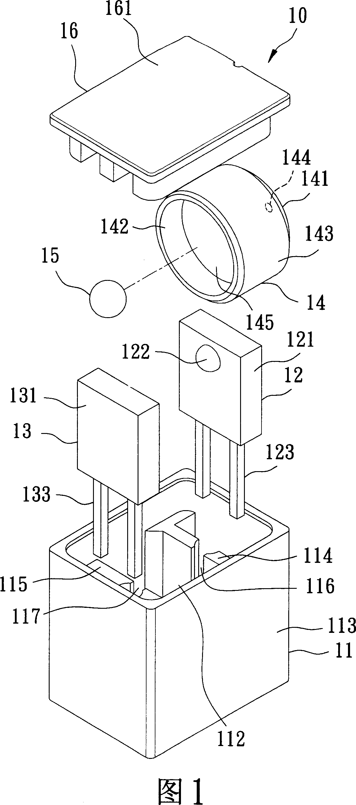
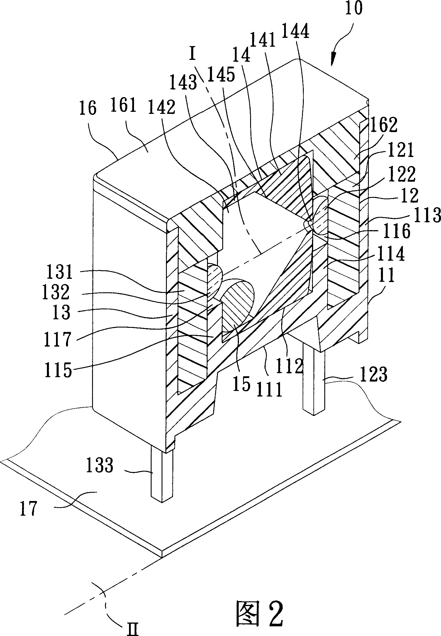
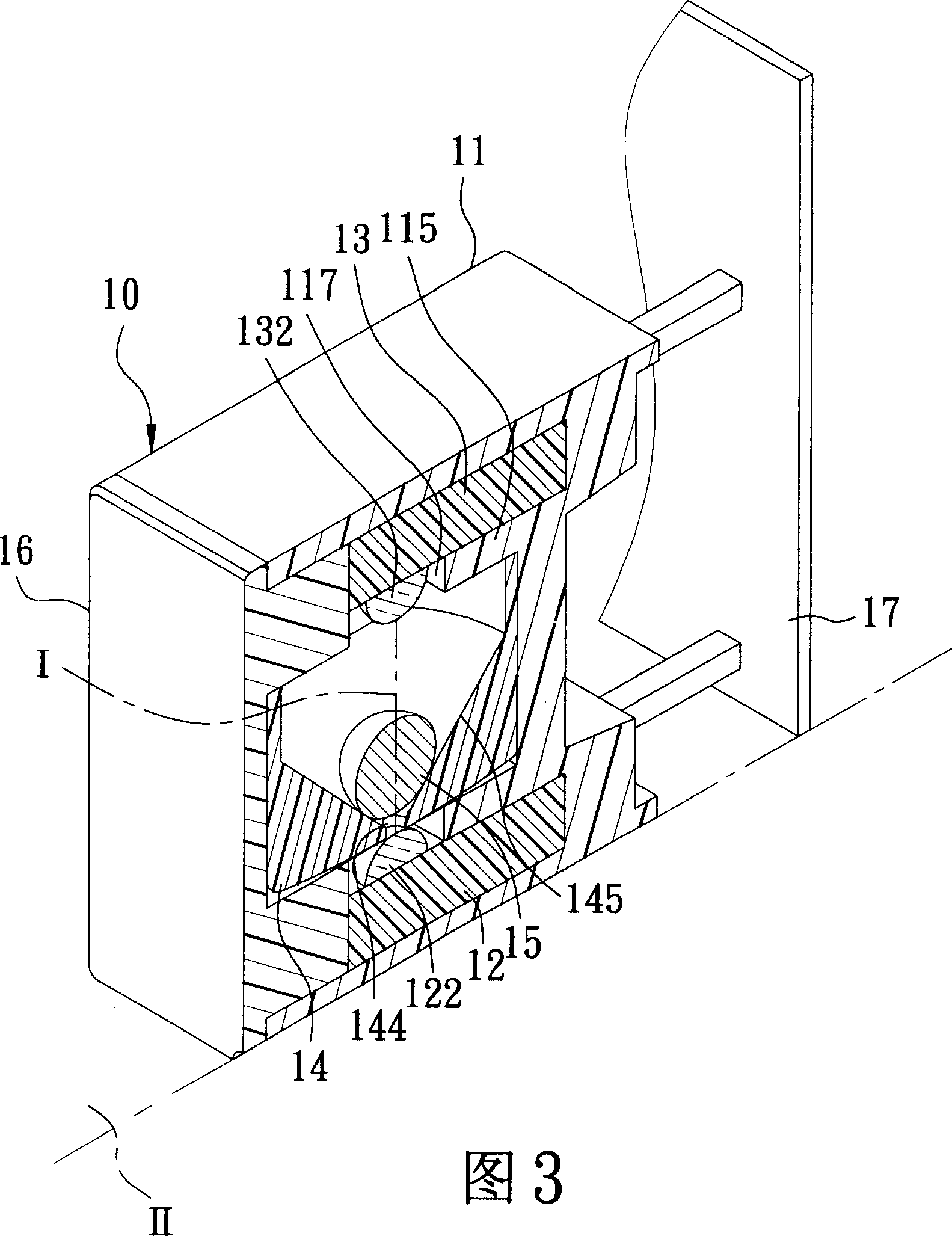
[0036] As shown in Figures 4, 5, and 6, a first preferred embodiment of the ball switch 2 of the present invention includes a base 20, a transmitter 30 and a receiver 40 respectively mounted on the base 20 and spaced apart from each other, a The receiving unit 50 installed in the base 20 , a ball 60 rotatably installed in the receiving unit 50 , and a set of outer cover 70 placed on the base 20 .

[00...


PUM


Abstract

The invention discloses a ball switcher, which comprises the following parts: base, a seal launcher and a receiver assembled in the seal container jacketed in the base to mate mutually, seal container jacketed in the base to contain ball and bearing unit, lid to cover the base, wherein the inner cylinder contains a basic wall and optical inlet hole through the basic wall to face the straight communicating path; the inner lid concludes a cap, a self-sealing moulding projection and optical outlet hole through the projection to face the straight communicating path; the ball rolls between the baffling position and the separating position of straight communicating path. The invention can prevent ball not lying at the baffling position, which can reduce the error movement generating rate.

Description

technical field [0001] The invention relates to a switch, in particular to a ball switch which utilizes a transmitter, a receiver and a ball to achieve action and signal change. Background technique [0002] As shown in Figures 1 and 2, the ball switch 10 of the US No. 6,800,841 patent created by the creator and approved has a base 11, a transmitter 12 and a receiver 13 respectively installed on the base 11 and spaced from each other , an inner cylinder 14 installed in the base 11 , a ball 15 that is rotatably located in the inner cylinder 14 , and a cover 16 that covers the base 11 . [0003] The base 11 has a bottom wall 111, a surrounding wall 113 extends from the periphery of the bottom wall 111 and cooperates with the bottom wall 111 to form a chamber 112, respectively extends from the bottom wall 111 and is located in the chamber 112 A first spacer 114 and a second spacer 115 that are spaced apart from each other, and a first slot 116 and a second slot 117 that are re...

Claims


Application Information

Patent Timeline
Patent Type & Authority Applications(China)
IPC IPC(8): H03K17/968G02B6/42H01L31/167
Inventor 周添铭
Owner ONCQUE CORP
Why Eureka
Try Eureka