
Device for determining and/or monitoring a volumetric and/or mass flow

A mass flow and volume technology, applied in the direction of measuring flow/mass flow, measuring device, liquid/fluid solid measurement, etc., can solve the problems of measurement value deviation and achieve high stability

Inactive Publication Date: 2007-11-28
ENDRESS HAUSER FLOWTEC AG
View PDF1 Cites 4 Cited by
  • Summary
  • Abstract
  • Description
  • Claims
  • Application Information

AI Technical Summary

Problems solved by technology

With this known method for the correction of non-linearities occurring in disturbed gas flows, significant measured value deviations can result due to incorrect assignment of the Reynolds number

Method used


Image

  • Device for determining and/or monitoring a volumetric and/or mass flow
  • Device for determining and/or monitoring a volumetric and/or mass flow
  • Device for determining and/or monitoring a volumetric and/or mass flow

Examples


Embodiment Construction

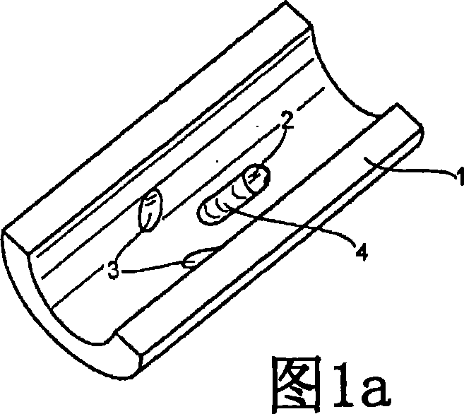
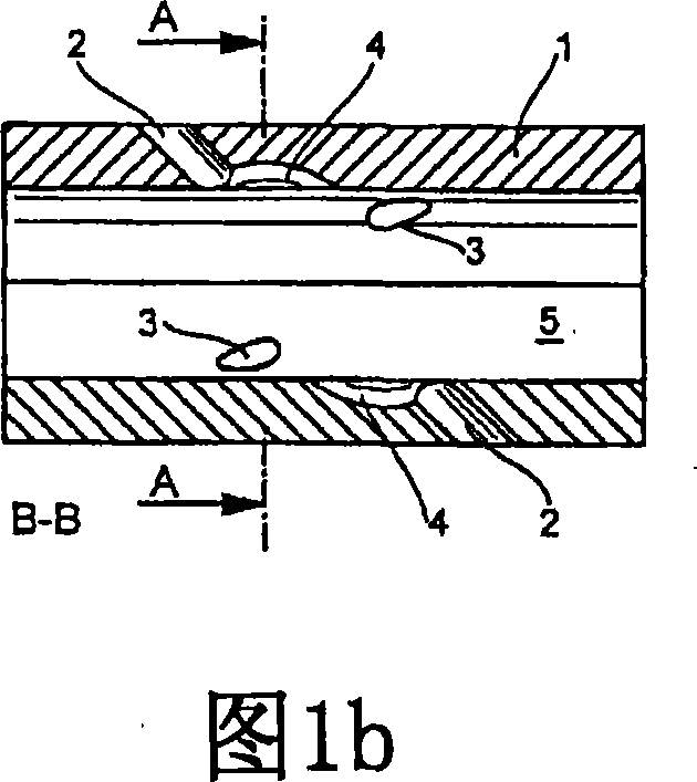
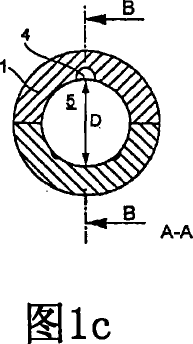
[0074] Fig. 1 to Fig. 9 are nine advantageous structural schematic diagrams of the online flowmeter 10 of the present invention. The flow meters 10 shown each comprise three measuring paths, ie acoustic paths. The volume or mass flow is preferably determined by the travel time difference method. The invention can in principle be applied to each ultrasonic flow meter 9 , 10 completely independently of the chosen measurement or analysis method. Even though only a flow meter with at least two ultrasonic sensors is described below, the ultrasonic flow meters 9 , 10 can also be designed with only one ultrasonic sensor 7 or with an optimized sensor housing for an acoustic path.

[0075] Figures 1a to 9a each show a top view of a cut-away measuring tube 1 according to the inventive concept. Each of the measuring tubes includes 3 bores with an at least partially optimized sensor housing 4 . In the example shown, the deformation 4 penetrates into the tube wall of the measuring tube ...


PUM


Abstract

The invention relates to an ultrasonic flowmeter (9) for determining and / or monitoring the volumetric and / or mass flow of a measuring medium (5) through a pipe or a measuring tube (1). According to the invention, the wall of the pipe or measuring tube (1) comprises a deformation (4) or deformations in the vicinity of the defined sensor position of the ultrasonic sensor (7) and / or in the vicinity of the sonic path of the ultrasonic signals of the ultrasonic sensor(s) (7). Said deformation or deformations is / are configured and / or located in such a way that the flow speed of the measuring medium (5) that is measured in the sonic path, or in the case of several ultrasonic sensors (7) the flow speeds of the measuring medium (3) that are measured in the sonic paths and / or the cumulative flow speeds of the measuring medium at least approximately corresponds or correspond to the average flow speed of the measuring medium (3) that is calculated over the area of the pipe or measuring tube (1).

Description

technical field [0001] The invention relates to a device for determining and / or monitoring the volumetric and / or mass flow of a measuring medium through a conduit or measuring tube, wherein the measuring medium flows through the measuring medium substantially in a flow direction parallel to the longitudinal axis of the measuring tube tube, the device has at least one ultrasonic sensor which transmits and / or receives ultrasonic measuring signals in at least one defined acoustic path, wherein the at least one ultrasonic sensor is placed in the measuring tube wall at a defined sensor position or in The outer wall of the conduit, and the device has a regulating / evaluating unit, which determines the volume and / or mass flow of the measuring medium through the conduit or through the measuring tube on the basis of the ultrasonic measurement signal. The measuring medium can be liquid, gas or vapor medium. Background technique [0002] In online flow meters, ultrasonic sensors are co...

Claims


Application Information

Patent Timeline
Patent Type & Authority Applications(China)
IPC IPC(8): G01F1/66
CPCG01F1/662
Inventor 托马斯·弗勒利希阿希姆·维斯特安德里亚斯·贝格尔托尔斯滕·施特龙茨奥利弗·贝尔贝里戈
Owner ENDRESS HAUSER FLOWTEC AG
Learn More