
Coupling and gear transmission device having the same

A technology of couplings and gears, applied in the field of couplings, can solve problems such as tooth surface contact, unbalanced load, etc., and achieve lower costs, increased stability and reliability, and simplified lubrication devices Effect

Inactive Publication Date: 2010-05-12
MITSUBISHI HEAVY IND LTD
View PDF6 Cites 0 Cited by
  • Summary
  • Abstract
  • Description
  • Claims
  • Application Information

AI Technical Summary

Problems solved by technology

[0027] Therefore, with the conventional technology, the following situation may occur: the first-stage meshing portion A composed of the first pinion 3 and the first wheel 4 and the second-stage meshing composed of the second pinion 5 and the second wheel 6 cannot be smoothly performed The axial alignment of part B, and the load on the left and right teeth of the herringbone gear of the first-stage meshing part A or the second-stage meshing part B is unbalanced, resulting in partial contact of the tooth planes and cracking of the gear
[0028] Said Japanese Published Patent Application No. 2004-138608 does not provide any teaching for solving this problem

Method used


Image

  • Coupling and gear transmission device having the same
  • Coupling and gear transmission device having the same
  • Coupling and gear transmission device having the same

Examples


Embodiment Construction

[0060] Preferred embodiments of the present invention will now be described in detail with reference to the accompanying drawings. However, unless otherwise specified, the dimensions, materials, relative positions, etc. of the constituent parts in the embodiments should be understood as illustrative only, and should not be construed as limiting the scope of the present invention.

[0061] Figure 6 is a partially cutaway external perspective view of a secondary reduction unit for a vessel fitted with a steam turbine as the main propulsion engine.

[0062] exist Figure 6 Among them, reference numeral 1 is a high-pressure side input shaft connected to a high-pressure turbine (not shown in the figure), and reference numeral 2 is a low-pressure side input shaft connected to a low-pressure turbine (not shown in the figure).

[0063] The two-stage reduction gear has a first-stage engaging portion A on the bow side and a second-stage engaging portion B on the stern side.

[0064] A...


PUM


Abstract

A coupling connecting an input side rotating shaft to an output side rotating shaft and transmitting the rotational force of the input side rotating shaft to the output side rotating shaft and a geartransmission device having the coupling. In the coupling, a diaphragm formed of a flexible material is interposed between the input side rotating shaft and the output side rotating shaft so as to be deformed in the axial directions of these shafts, and the input side rotating shaft is connected to the output side rotating shaft through the diaphragm so as to be axially moved relative to each other. Thus, the durability of the coupling and the reliability of power transmission of the coupling can be increased.

Description

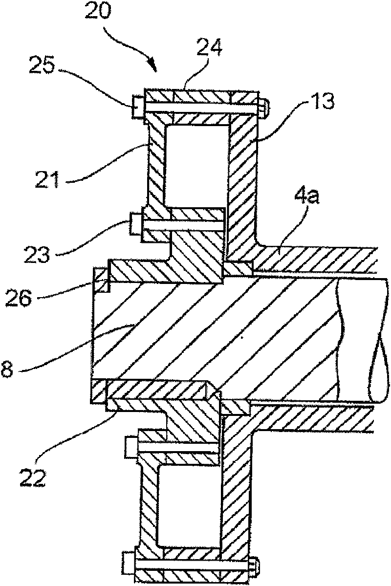
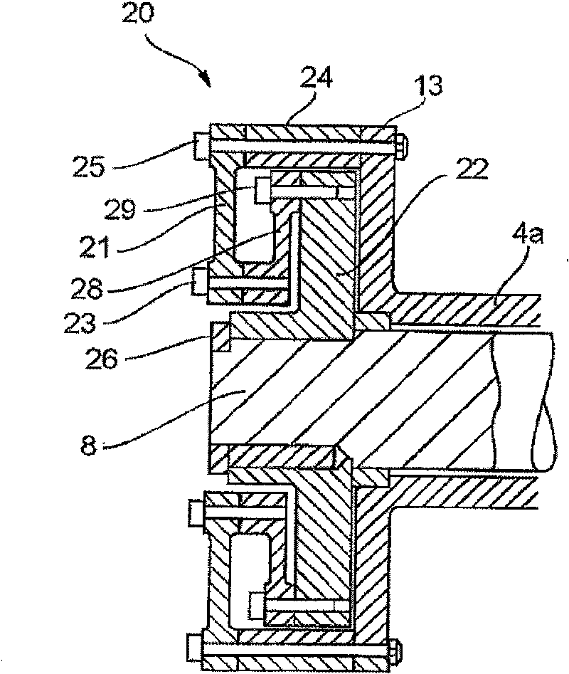
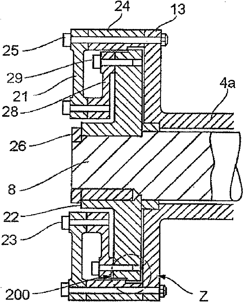
technical field [0001] The present invention relates to a coupling for connecting an input side rotary shaft to an output side rotary shaft in a gear transmission such as A ship speed reduction device for a ship in which a steam turbine is installed as a main propulsion engine, and relates to a gear transmission device having the coupling. Background technique [0002] The speed reduction of the steam turbine installed in the ship as the main propulsion engine is reduced from the high speed of the steam turbine to an extremely low speed of 100rmp or less with a large reduction ratio through the speed reduction device of the ship, so it is used in the speed reduction device of the ship Helical gears for smooth meshing of gears. [0003] On helical gears, a thrust Fa is applied in addition to a tangential force Ft, through which torque is transmitted. Thrust Fa is [0004] Fa=Ft·tanβ [0005] where β is the helix angle of the transmission gear. [0006] In a ship reductio...

Claims


Application Information

Patent Timeline
Patent Type & Authority Patents(China)
IPC IPC(8): F16D3/74
CPCF16D3/76F16D3/74F16D3/50
Inventor 近藤武志藤川卓尔
Owner MITSUBISHI HEAVY IND LTD
Learn More