Bicycle driven by rowing and sliding

A technology for driving bicycles and forks. It is applied to bicycles, bicycle accessories, bicycle saddles, etc. It can solve the problems of fixed seats, unsatisfactory centrifugal force, and inability to fully exert the strength of feet and legs.

Inactive Publication Date: 2007-12-12
张东
View PDF0 Cites 2 Cited by
  • Summary
  • Abstract
  • Description
  • Claims
  • Application Information

AI Technical Summary

Problems solved by technology

[0002] At present, the pull-rod and rocker-type tricycles have become good helpers for the disabled, but the seats of these bicycles are fixed, so they cannot give full play to the strength of the feet and legs.
And although the three-wheel sliding driving bicycle of our previous public invention has solved the above-mentioned problems, it is not ideal to overcome the centrifugal force when turning, and the force of the chain plate is not good.

Method used


Image

  • Bicycle driven by rowing and sliding
  • Bicycle driven by rowing and sliding

Examples


Embodiment Construction

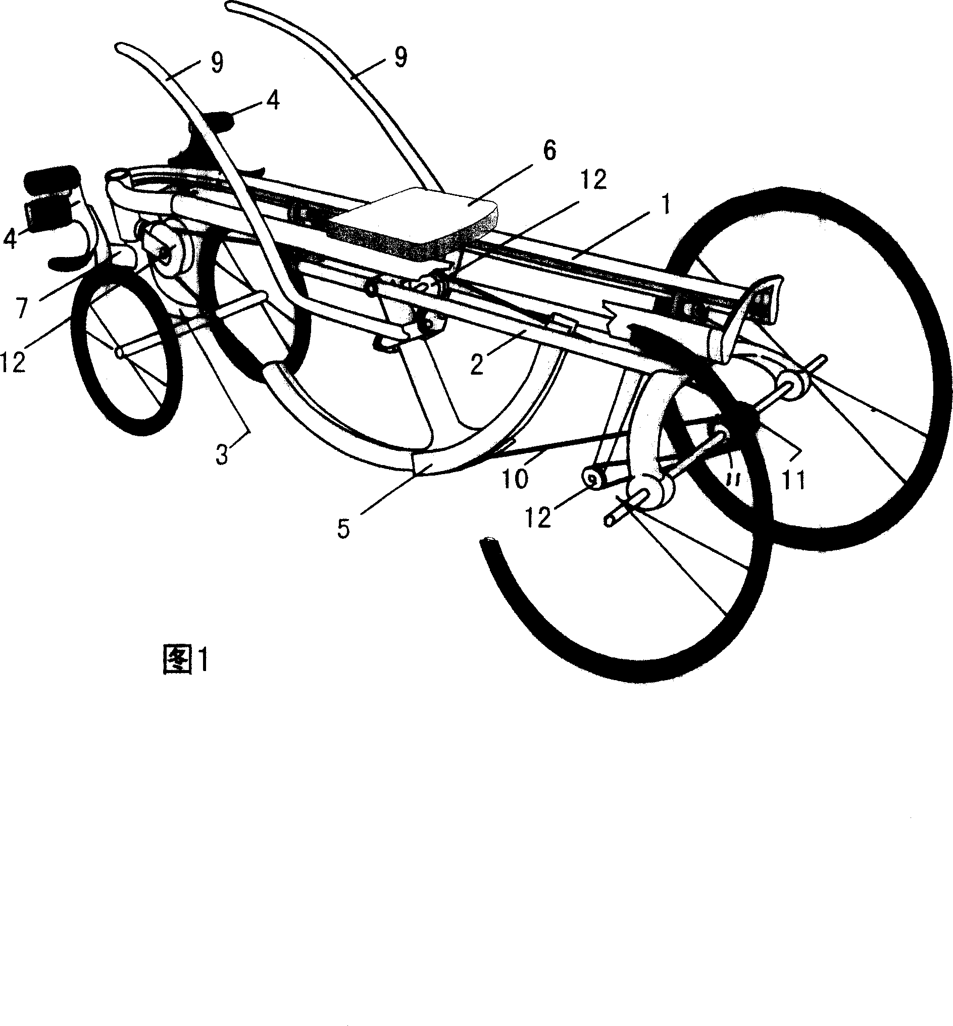
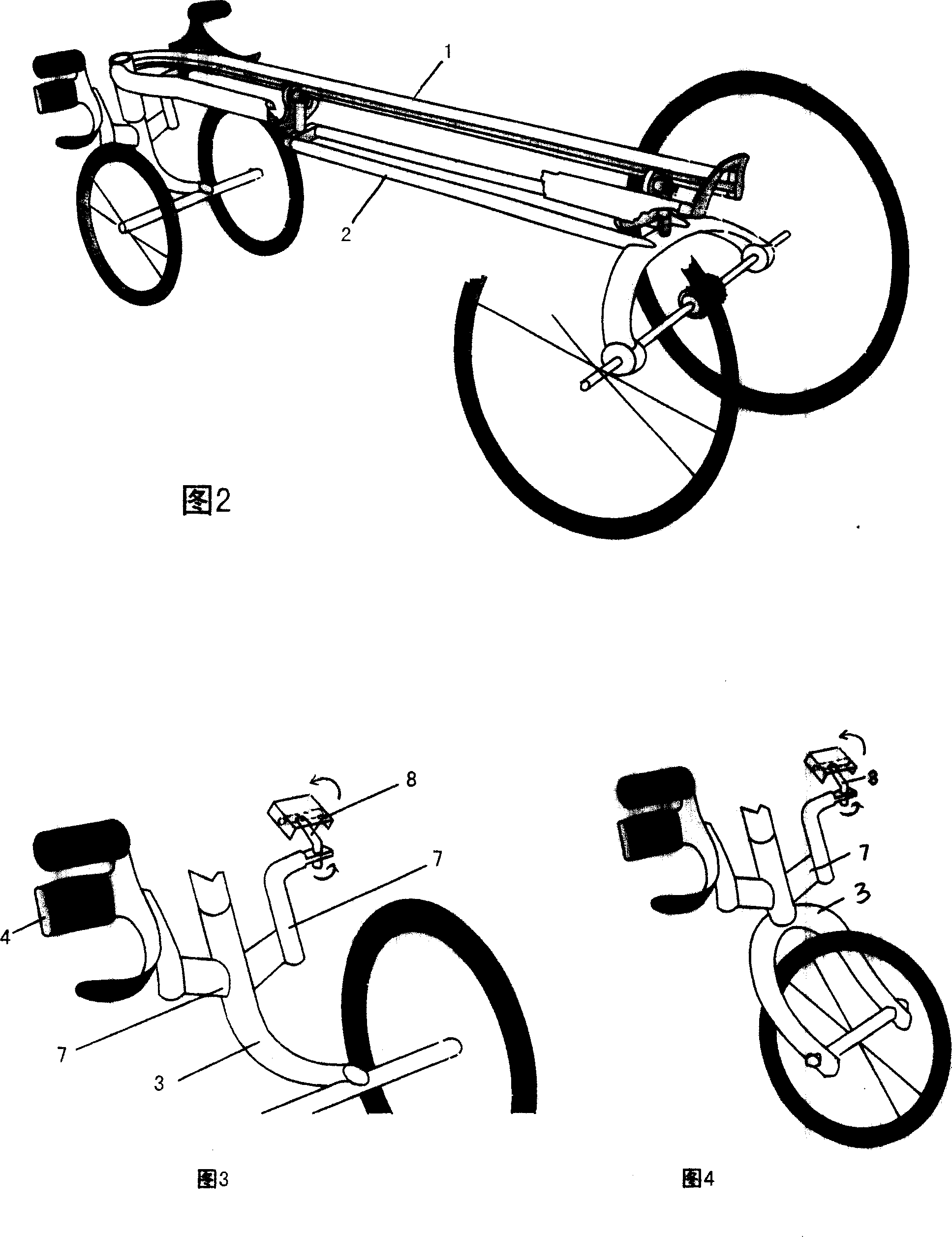
[0016] As shown in Figure 1, double parallel main beams [1] with seat slides are adopted, the front and rear parts of the main beam [1] are respectively connected with the front and rear parts of the double parallel auxiliary beams [2]. The front fork [3] of two wheels (Fig. 3) or one wheel (Fig. 4) front axle is fixedly equipped with beam [1] front end, and the rear axle of two wheels is equipped with at the secondary beam [2] rear end, and front fork [ 3] Pedals [4] steering devices are installed on both sides, double-slot chain disc [5] driving device is installed on the front of sub-frame [2], and sliding seat [6] is installed on the main beam [1]:

[0017] Pedal [4] steering device: the upper end of the front fork [3] is connected with the front end of the main beam [1], the lower end is connected with the front axle, and the two ends of the steering beam [7] of the front fork [3] are respectively connected with the crankshaft [ 8] connection, the other end of the cranksh...


PUM


Abstract

The invention relates to a slide drive bicycle. It solves the centrifugal force issue while turning and monotonic in power. It uses dual parallel main beam, front and rear of the main beam connected to the front and rear of the sub beam in parallel, front of the main beam fixed with two wheels or a wheel front fork, rear of the sub beam installed with rear shaft of two wheels, both sides of the front fork installed with pedal steering device, front of the sub beam installed with dual slot chain plate driving device, main beam installed with slide seat.

Description

Technical field: [0001] The invention relates to a bicycle device, in particular to a sliding-driven bicycle capable of realizing interesting fitness exercises. Background technique: [0002] At present, pull-rod type and rocker type tricycles have all become good helpers for the disabled to walk instead of, but this kind of car seat is fixed, so the strength of feet and legs cannot be fully exerted. And though our previously disclosed three-wheel skating drive bicycle has solved the above-mentioned problems, it is not ideal to overcome the centrifugal force when turning, and the chain plate is not good for exerting force. Invention content: [0003] The present invention is a research aimed at the above problems, and its purpose is to replace the original single beam structure with the combination of the main beam and the auxiliary beam, replace the original single-structure chain disk device with the chain disk of the double-slot structure, and use the arc-shaped long T...

Claims


Application Information

Patent Timeline
IPC IPC(8): B62K5/00B62M1/16B62J1/00
Inventor 张楠张北李四马张东
Owner 张东
Why Eureka
Try Eureka