A magnet assembly installation method for a permanent magnet motor

A technology of magnet components and installation methods, applied in the manufacture of stator/rotor bodies, etc., can solve problems such as difficulties, centrifugal force and high temperature of magnetic poles, and achieve the effect of overcoming magnetic field strength

Active Publication Date: 2011-12-21
GUANGDONG MINGYANG WIND POWER IND GRP CO LTD
View PDF4 Cites 2 Cited by
  • Summary
  • Abstract
  • Description
  • Claims
  • Application Information

AI Technical Summary

Problems solved by technology

[0005] Using the above method to solve the problems of the centrifugal force of the rotor magnetic pole of the medium and high-speed permanent magnet generator, the unilateral magnetic pulling force and the high temperature of the flow field, it is necessary to fix it mechanically. At the same time, the magnetic loss and magnetic short-circuit saturation must also be considered. In addition, the magnetic poles must be made It is also very difficult to form an oblique pole at a certain angle with the axis

Method used


Image

  • A magnet assembly installation method for a permanent magnet motor
  • A magnet assembly installation method for a permanent magnet motor
  • A magnet assembly installation method for a permanent magnet motor

Examples


Embodiment Construction

[0027] The present invention is described in detail below in conjunction with accompanying drawing:

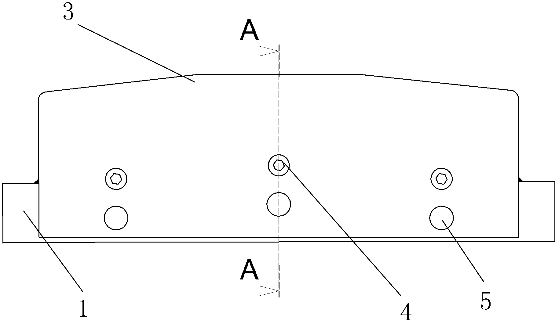
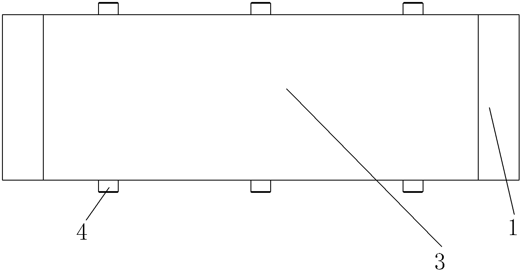
[0028] Such as Figure 1-4 As shown, a magnet assembly installation method of a permanent magnet motor includes the following steps:

[0029] First, the magnet 2 is placed on the magnet base 1 so that the periphery of the magnet 2 is aligned with the periphery on the surface of the magnet base 1 .

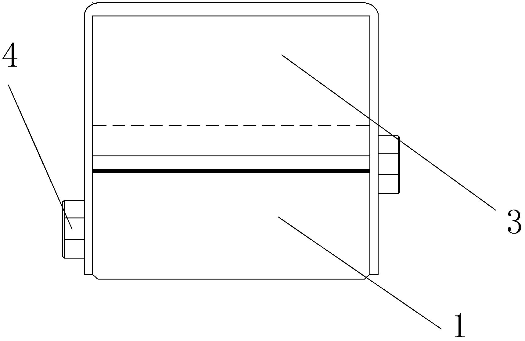
[0030] Secondly, insert the magnet protection cover 3 of non-magnetic material into the magnet 2, so that the magnet protection cover 3 completely covers the magnet 2, and use the fixing screw 4 to pass through the magnet protection cover 3 and screw it into the magnet base 1, so that the magnet 2 is fixed On magnet base 1. Such as Figure 4 shown.

[0031] Thirdly, the magnet protection cover 3 is connected with the magnet base 1, so that the magnet protection cover 3 and the magnet base 1 are connected as a whole.

[0032] Its four, on the side of the magnet protection cover...


PUM


Abstract

The invention relates to a method for installing magnet components of a permanent magnet motor. The method comprises the following steps that firstly a magnet is placed on a magnet base so as to aim the periphery of the magnet at the periphery on the surface of the magnet base; secondly a magnet protective cover of a non-magnetic conductive material is sleeved in the magnet, the magnet is fully covered by the magnet protective cover, fixing bolts are utilized to pass through the magnet protective cover and are screwed in the magnet base so as to fix the magnet on the magnet base; thirdly the magnet protective cover is connected with the magnet base so as to integrally connect the magnet protective cover with the magnet base; and fourthly escaping fixing screw nail holes used for escaping and fixing screw nail caps are formed at the side of the magnet protective cover when a plurality of magnet protective covers are connected in sequence, and counter bores are also formed on the magnet base corresponding to the escaping fixing screw nail holes, partial of the fixing screw nail caps are also arranged in the counter bores, and the magnet components are finished installing.

Description

【Technical field】 [0001] The invention relates to a method for installing a magnet assembly of a permanent magnet generator, in particular to a method for installing a large-mass magnet assembly for a rotor of a high-power, medium-high speed permanent magnet generator. 【Background technique】 [0002] High-power, medium- and high-speed permanent magnet generators usually use tile-shaped or rectangular NdFeB magnets as the magnetic poles of the rotor. The magnetic poles are installed on the rotor body of the permanent magnet generator, and its magnetization direction is usually radial. Generally, there is an adhesive bonding method, which often cannot solve the requirements of large-mass magnet fixing. Large-mass magnet fixing needs to solve the problems of centrifugal force, unilateral magnetic pull force and high temperature of the flow field, especially for the 20-year operation of wind turbines. Require. [0003] In the previous technology, for the tile-shaped or rectang...

Claims


Application Information

Patent Timeline
Patent Type & Authority Applications(China)
IPC IPC(8): H02K15/03
Inventor 关玉
Owner GUANGDONG MINGYANG WIND POWER IND GRP CO LTD
Why Eureka
Try Eureka