Semi-embedded structure of rotor of permanent magnet synchronous motor

A permanent magnet synchronous motor, embedded technology, applied in the direction of magnetic circuit shape/style/structure, magnetic circuit rotating parts, etc., to achieve the effect of great flexibility, easy process and cost reduction

Inactive Publication Date: 2011-04-27
TIANJIN SANTROLL ELECTRIC SCI & TECH
View PDF2 Cites 2 Cited by
  • Summary
  • Abstract
  • Description
  • Claims
  • Application Information

AI Technical Summary

Problems solved by technology

The current commonly used permanent magnet synchronous motors use the above method on the stator, which has certain limitations on the larg

Method used


Image

  • Semi-embedded structure of rotor of permanent magnet synchronous motor
  • Semi-embedded structure of rotor of permanent magnet synchronous motor
  • Semi-embedded structure of rotor of permanent magnet synchronous motor

Examples


Embodiment Construction

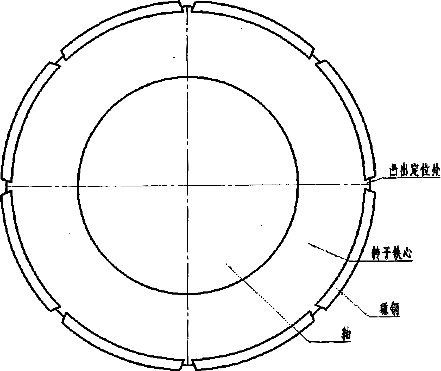
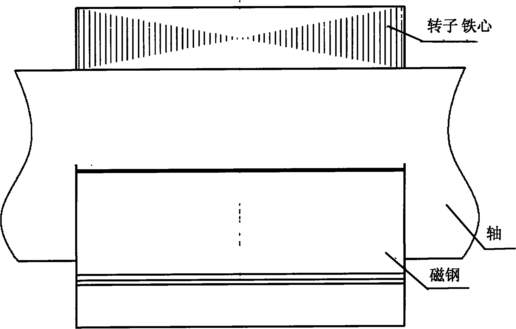
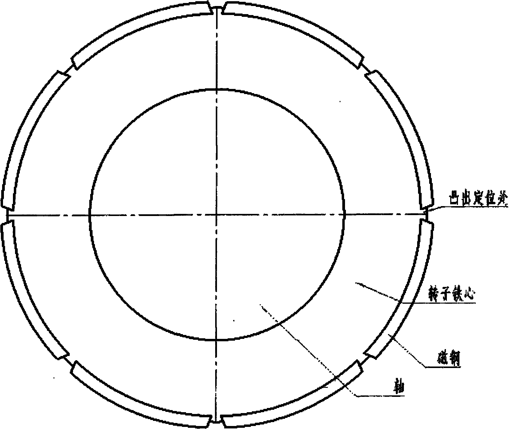
[0012] The present invention will be further described below in conjunction with accompanying drawing and specific embodiment:

[0013] Such as figure 1 , the outer surface of the rotor core is evenly distributed with protruding rotor teeth, tile-shaped magnetic steel is placed between adjacent rotor teeth, and the magnetic steel is half-embedded in the surface of the rotor core, which is closely attached to the surface of the rotor core, which can be extremely Greatly reduce the large magnetic flux leakage generated by the embedded, the iron cores on both sides clamp it, and apply general structural glue and curing agent on the inner surface of the magnetic steel and rotor core, so as to ensure the smooth operation of the motor above 10,000rpm.

[0014] Utilize the technical solution described in the present invention, or those skilled in the art design a similar technical solution under the inspiration of the technical solution of the present invention, and achieve the above...


PUM


Abstract

The invention relates to a semi-embedded structure of a rotor of a permanent magnet synchronous motor. The structure has the advantages of a convex type rotor and an inserting type rotor, thereby being capable of reducing the larger flux leakage caused by an embedded type rotor, and being capable of guaranteeing that an electric machine can stably run at more than 10000rpm. The structure is characterized in that the rotor of the permanent magnet synchronous motor is of the semi-embedded structure, and magnet steel is embedded in an iron core of the rotor, so that the rotor can not be thrown out caused by the overlarge centrifugal force when the rotor rotates at high speed. The semi-embedded structure of the rotor of the permanent magnet synchronous motor is convenient to machine, saves the material, avoids the flux leakage, improves the capability of the rotator, and is good for the popularization and the use of the high-efficiency permanent magnet synchronous motor.

Description

technical field [0001] The invention belongs to the technical field of permanent magnet synchronous motors, in particular to a novel rotor structure design of a permanent magnet synchronous motor rotor. Background technique [0002] Now commonly used permanent magnet synchronous motor rotor core sub-surface type and plug-in type. Existing surface rotor structures are divided into protruding and embedded, and permanent magnets provide the direction of magnetic flux. Among them, tile-shaped magnetic steel is pasted on the surface of the protruding rotor core, and the outer surface of the permanent magnet and the inner circle of the stator core are generally only covered with a non-magnetic cylinder for protection, or the surface of the permanent magnet pole is covered with latitude-free glass. The ribbon is used as a protective layer to prevent the rotor magnetic steel from detaching from the rotor core under the joint action of centrifugal force and electromagnetic torsion w...

Claims


Application Information

Patent Timeline
IPC IPC(8): H02K1/27
Inventor 陈鹏王晔辉
Owner TIANJIN SANTROLL ELECTRIC SCI & TECH
Why Eureka
Try Eureka