Side-wise rotary type automatic ejection pick-up head

An automatic pop-up, camera technology, applied in the direction of image communication, color TV parts, TV system parts, etc., can solve problems such as easy wear and tear

Inactive Publication Date: 2007-12-12
LG ELECTRONICS (CHINA) R&D CENT CO LTD
View PDF0 Cites 14 Cited by
  • Summary
  • Abstract
  • Description
  • Claims
  • Application Information

AI Technical Summary

Problems solved by technology

[0002] In the past, the cameras were all designed in one piece, and the mirror surface was exposed, which was easy to wear and tear

Method used


Image

  • Side-wise rotary type automatic ejection pick-up head
  • Side-wise rotary type automatic ejection pick-up head
  • Side-wise rotary type automatic ejection pick-up head

Examples


Embodiment Construction

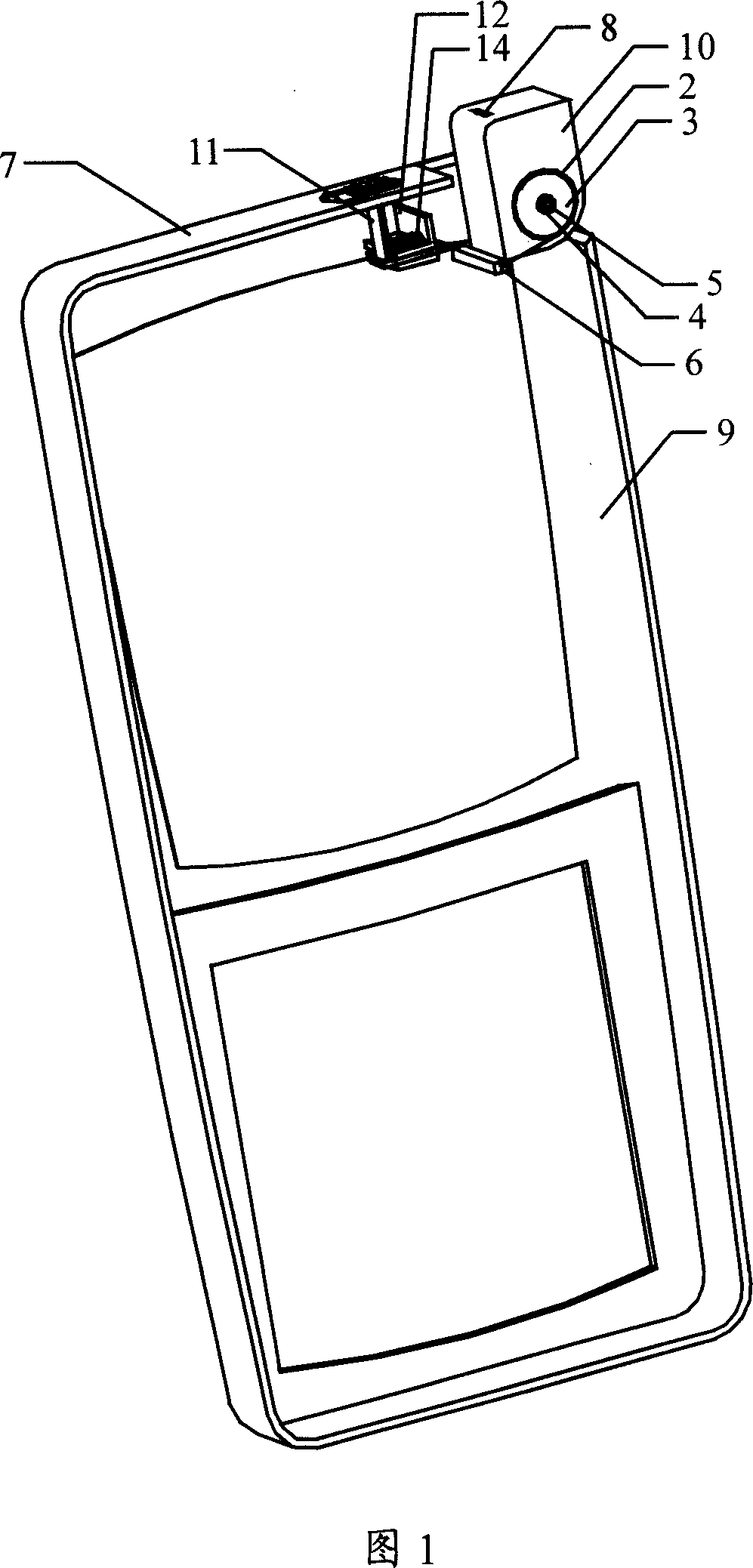
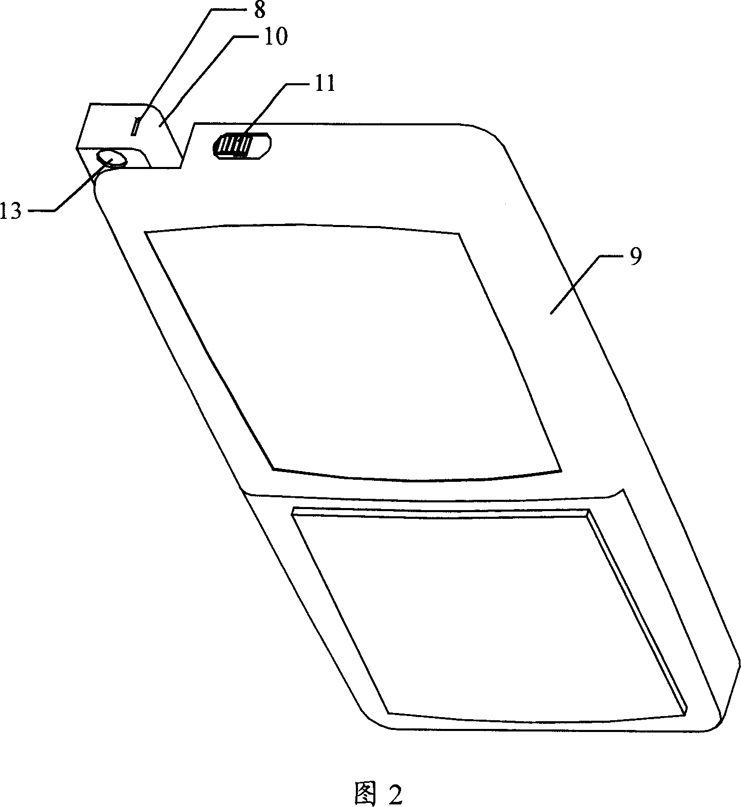
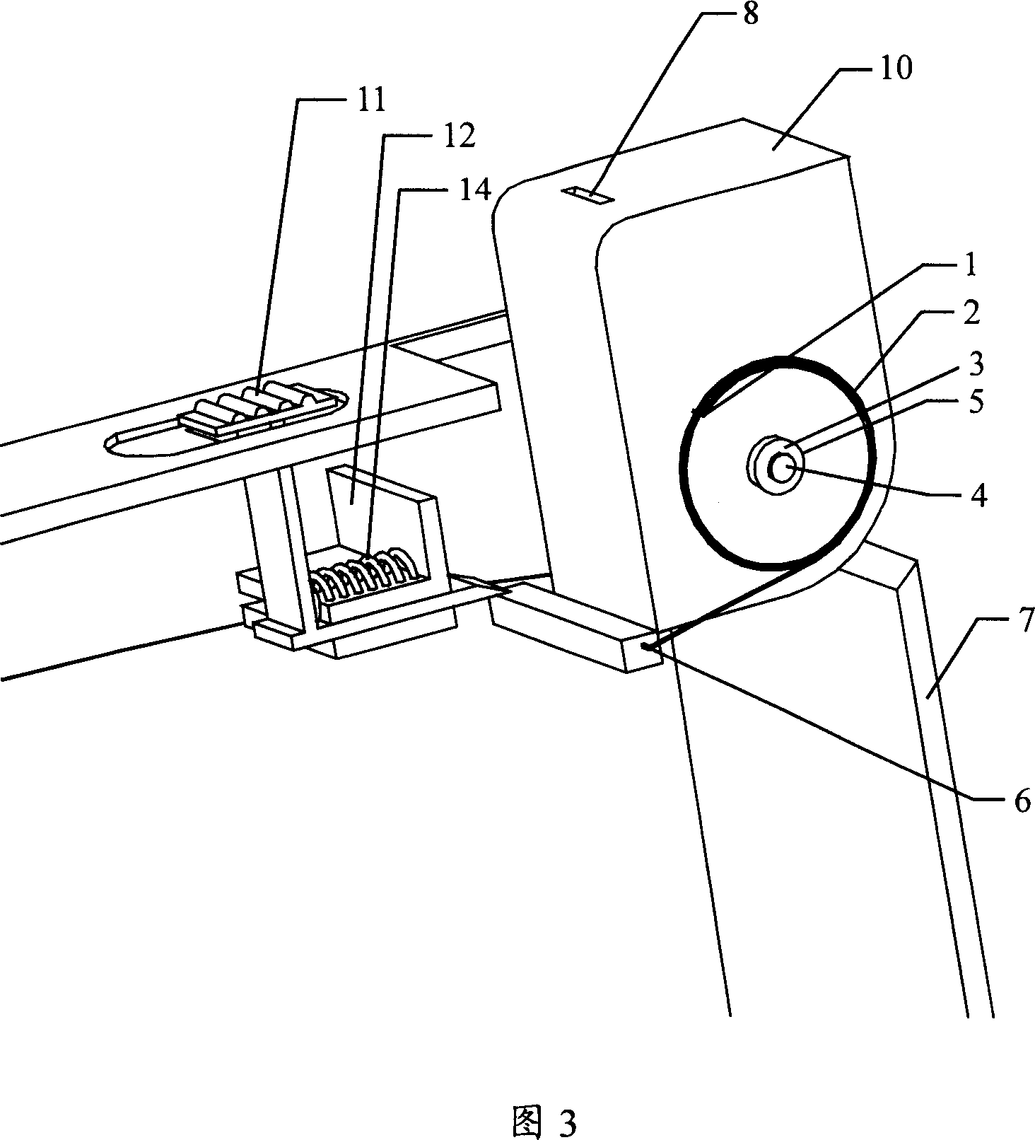
[0021] See attached drawings 1-5.

[0022] Described mobile terminal uses the camera head of lateral rotation type automatic pop-up to contain:

[0023] The camera 10 is rotatably connected to the casing 7. In the reset state of the camera, the camera 10 is installed in the protective cavity above the casing 7; in the working state, it rotates sideways and ejects;

[0024] Working spring 2, two ends are respectively connected on camera 10 and casing 7, when camera 10 is in reset state, working spring 2 is in stretched state, when camera 10 is in working state, working spring 2 is in stretched state;

[0025] The guide rail 12 is composed of two parallel sub-rails and is fixed on the casing 7;

[0026] Trigger key 11, when the camera 10 is in the reset state, the trigger key 11 locks the camera 10 under the guidance of the guide rail 12; when the camera 10 is in a working state, the trigger key 11 releases the camera 10;

[0027] The return spring 14 is connected to the trigg...


PUM


Abstract

The moving terminal camera automatic spring technique features in the camera being able to spring in rotation, working spring with both ends connected to the shell of the moving terminal and the camera to allow the camera switching from the reset status to maintain the working status, two parallel guide track connected to the shell, trigger key to lock the camera when the camera is in reset status, and releasing the camera when it is in working state, and the reset spring with both ends connected to the trigger key and the said guide track to allow the trigger key reset. It can protect the camera.

Description

technical field [0001] The invention belongs to the technical field of mobile terminals, and in particular relates to the automatic pop-up technology of a camera. Background technique [0002] In the past, the camera was designed as a whole, and the mirror surface was exposed, which was easy to wear and tear. Contents of the invention [0003] The purpose of the present invention is to provide a side-rotating automatic pop-up camera that can protect the camera from wear and tear. [0004] The feature of the present invention is that the camera head of the side-rotation type automatic pop-up for the mobile terminal contains: [0005] The camera is rotatably connected to the casing. In the reset state of the camera, the camera is installed in the protective cavity above the casing; in the working state, it rotates sideways and ejects; [0006] The two ends of the working spring are respectively connected to the camera and the inner surface of the casing, so that the camera...

Claims


Application Information

Patent Timeline
Patent Type & Authority Applications(China)
IPC IPC(8): G03B29/00H04N5/225H04M1/02
Inventor 王萌
Owner LG ELECTRONICS (CHINA) R&D CENT CO LTD
Why Eureka
Try Eureka