Axial gap motor

一种轴向间隙、类型的技术,应用在电气元件、机电装置、带有静止电枢和旋转磁体的同步电动机等方向,能够解决不能获得高输出等问题,达到高扭矩输出、实现小型化、高输出的效果

Inactive Publication Date: 2007-12-12
SUMITOMO ELECTRIC IND LTD
View PDF1 Cites 4 Cited by
  • Summary
  • Abstract
  • Description
  • Claims
  • Application Information

AI Technical Summary

Problems solved by technology

Therefore, high output can hardly be obtained, and the motor itself will be huge in the axial direction of the rotating shaft

Method used


Image

  • Axial gap motor
  • Axial gap motor
  • Axial gap motor

Examples


Embodiment Construction

[0093] Embodiments of the present invention will be described by referring to the drawings.

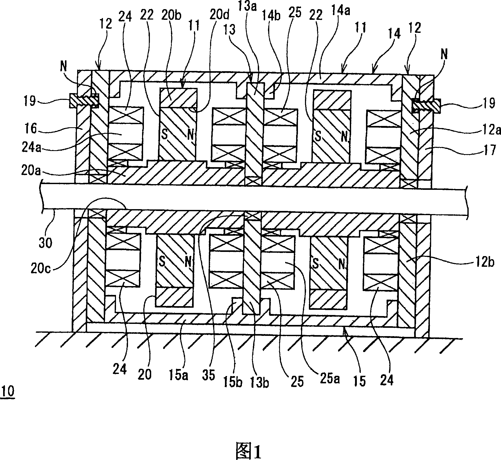
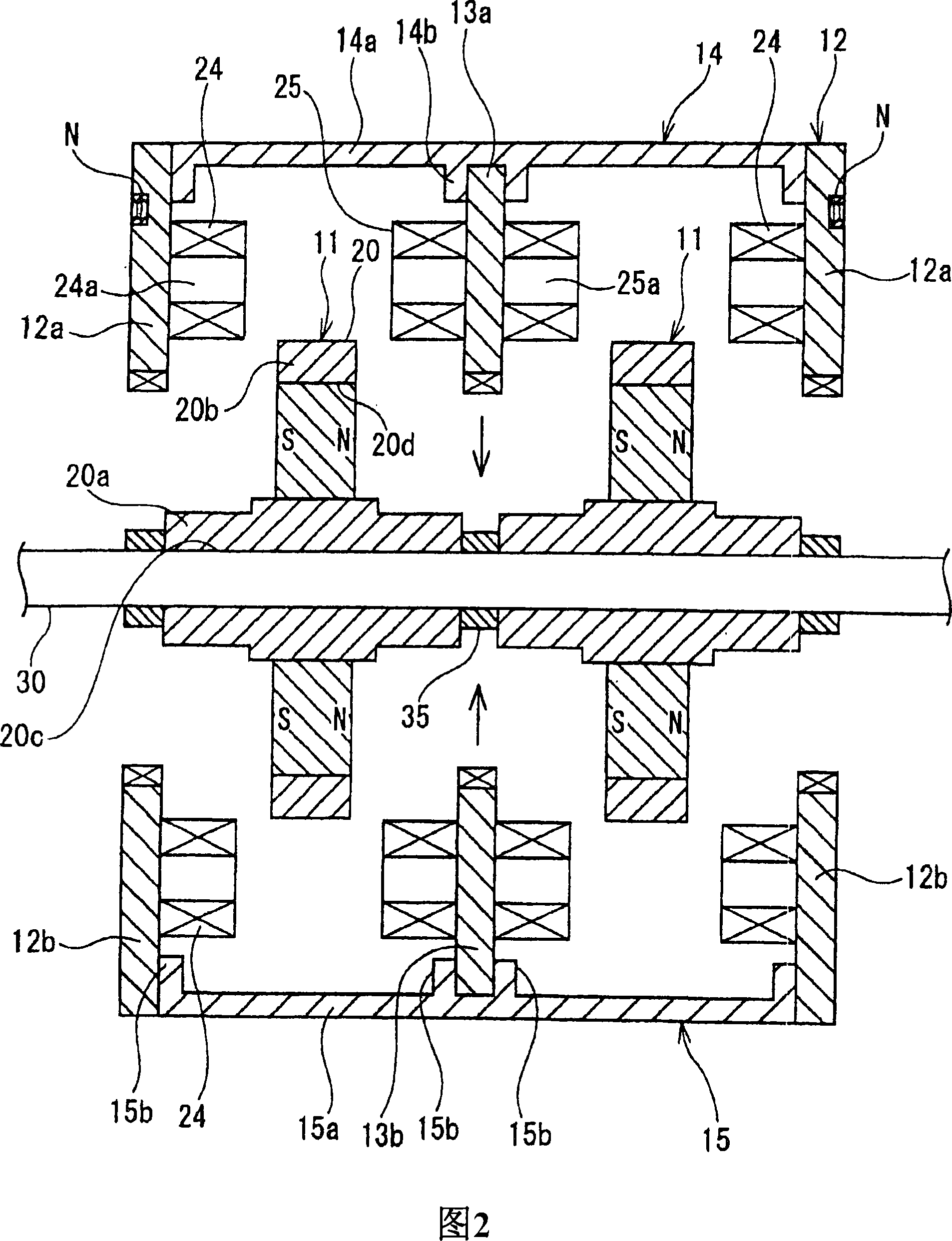
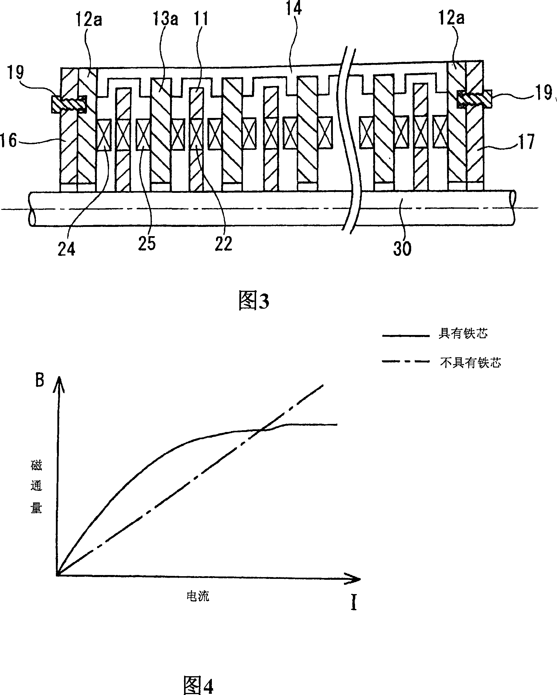
[0094] 1-3 show a series-coupled synchronous axial gap type electric machine 10 according to a first embodiment of the present invention. Furthermore, FIGS. 1 and 2 show an arrangement in which two rotors 11 , stators 12 at both axial ends, and an intermediate stator 13 are alternately arranged in the axial direction of the rotary shaft 30 for simplicity of illustration. However, as shown in FIG. 3 , a plurality of intermediate stators 13 are provided, and rotors 11 are disposed between adjacent stators 12 and 13 and between adjacent stators 13 and 13 , respectively.

[0095] The rotor 11 is fixed to the rotary shaft 30, and the stators 13 and 12 are arranged on both sides of the rotor 11 in the axial direction thereof with a required air gap. The stators 12 and 13 are connected to each other by upper and lower connection tools 14 and 15 , and the stators 12 at both axial ends are fi...


PUM


Abstract

A series coupling synchronous axial gap motor comprising a rotary shaft as a main shaft, and rotors and stators stacked alternately in the axial direction through required air gaps. The rotor is secured to the rotary shaft, the stator is arranged not to be interlocked with the rotary shaft, the rotor is fixed with a plurality of revolving field bodies around the axis, the stator is fixed with a plurality of armature coils around the axis that oppose the revolving field bodies through air gaps, and the armature coil is fixed with an air core or a core material of magnetic body.

Description

technical field [0001] The present invention relates to an axial gap type motor, in particular, to a series-coupled synchronous high-output motor suitable for use as a driving source for vehicles, ships, etc., especially for propelling large ships, such as government and Public office ships or passenger ships. Background technique [0002] Conventionally, as motors, there are radial gap type motors and axial gap type motors. A motor of radial gap type is a widely and commonly used motor in which a rotor is provided in a hollow member of a stator having a ring-shaped section whereby the direction of magnetic flux of a coil is directed in a radial direction. Meanwhile, an axial gap type motor, as disclosed in Japanese Unexamined Patent Application Publication No. 2004-140937, is configured such that the stators are arranged to face each other in the axial direction of the rotor, and the magnetic flux of the coils Directions are oriented as axial directions. [0003] In a co...

Claims


Application Information

Patent Timeline
Patent Type & Authority Applications(China)
IPC IPC(8): H02K21/24H02K1/12H02K55/04
CPCH02K21/24H02K55/04Y02E40/625Y02E40/60
Inventor 冈崎彻大桥绅悟杉本英彦竹田敏雄
Owner SUMITOMO ELECTRIC IND LTD
Why Eureka
Try Eureka