Condenser

A technology of condenser and condensate, applied in the direction of evaporator/condenser, steam/vapor condenser, refrigerator, etc., can solve the problems of contact between the surface of heat transfer area and gaseous fluid, etc.

Inactive Publication Date: 2007-12-19
XENESYS
View PDF1 Cites 10 Cited by
  • Summary
  • Abstract
  • Description
  • Claims
  • Application Information

AI Technical Summary

Problems solved by technology

This also raises the issue of contact hindrance between the surface of the heat transfer zone and the gaseous fluid

Method used


Image

  • Condenser
  • Condenser
  • Condenser

Examples


Embodiment Construction

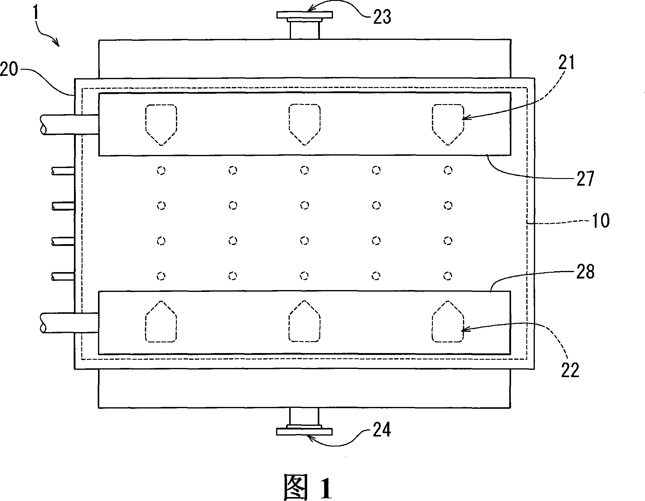
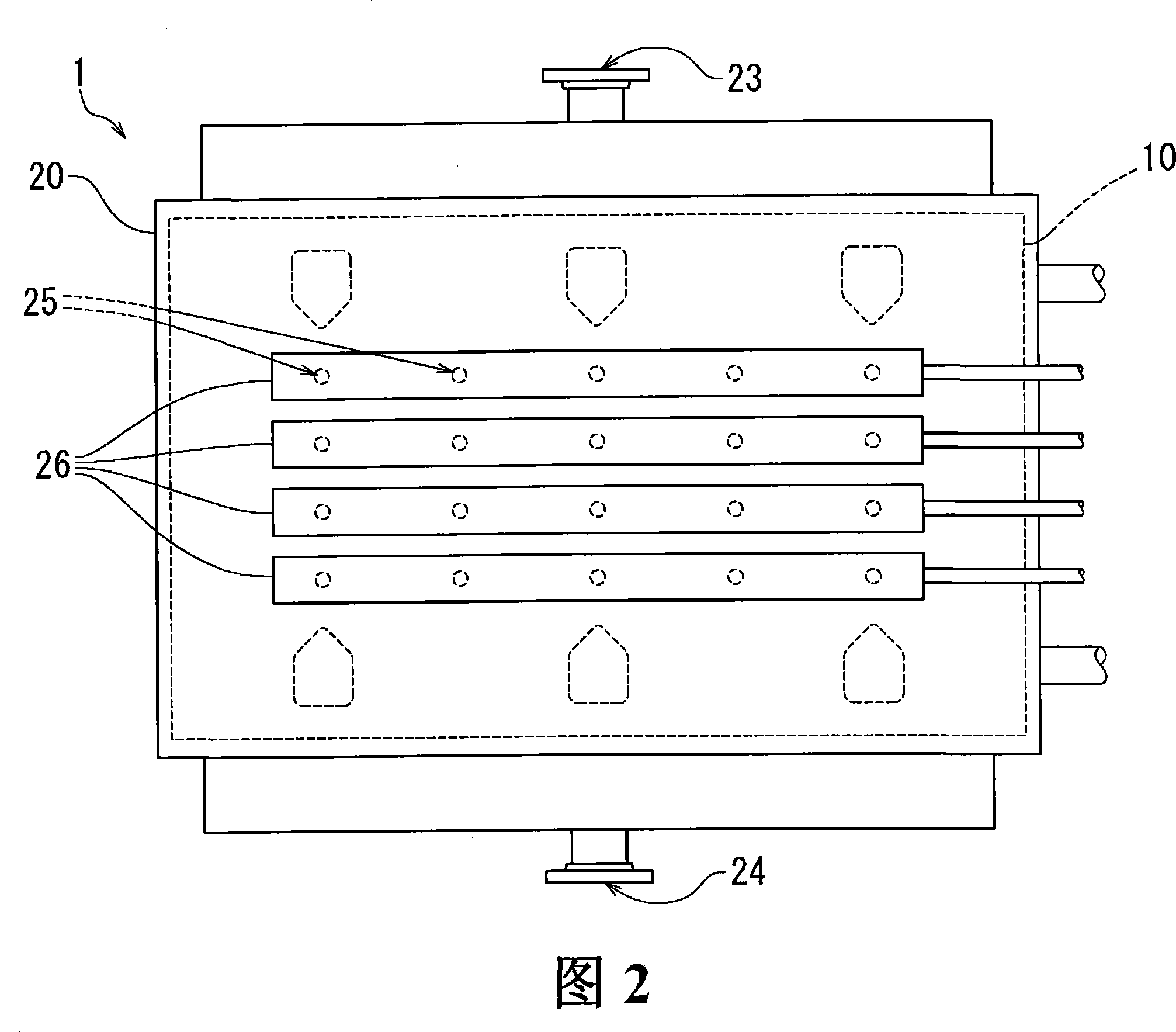
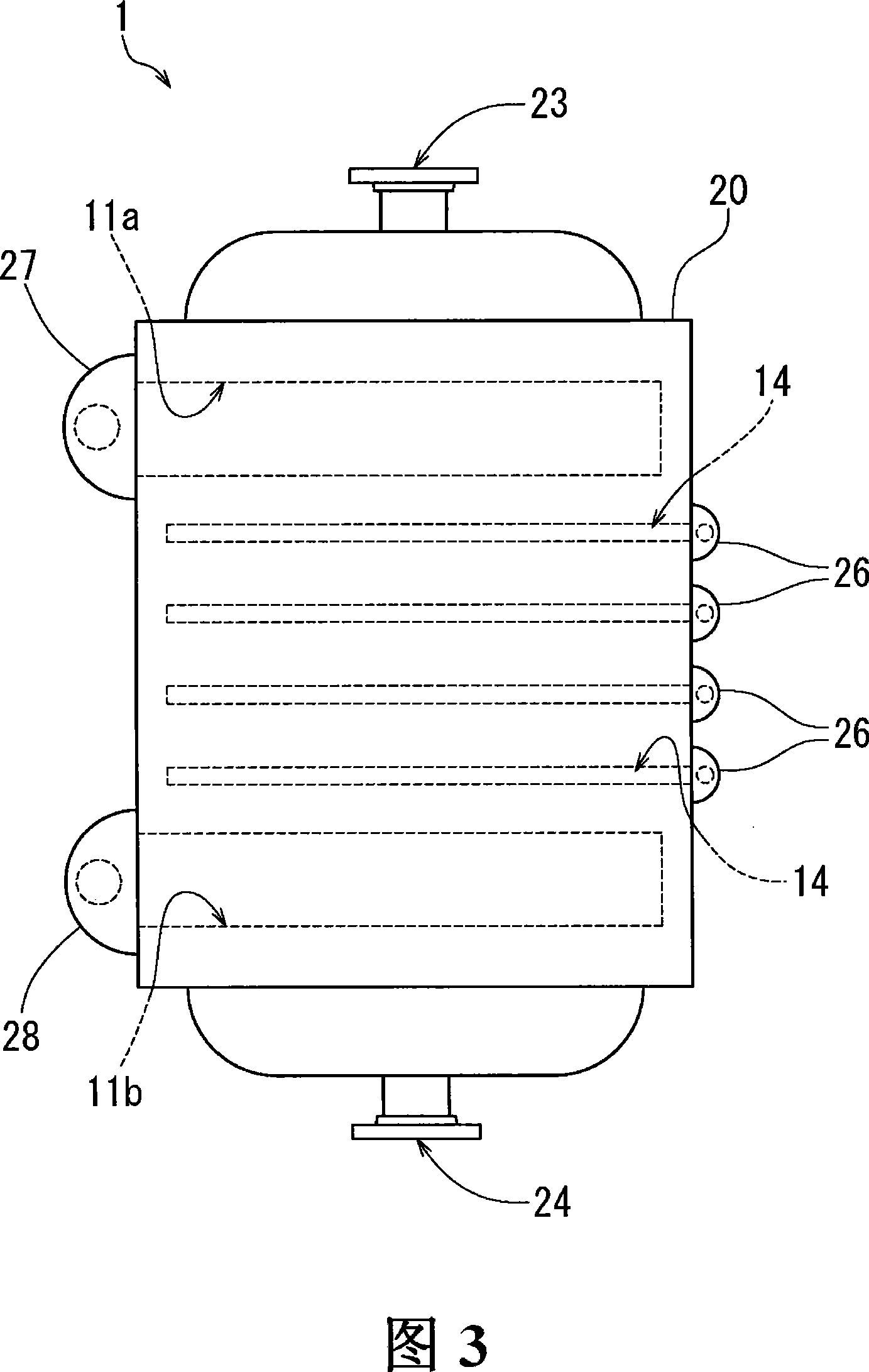
[0023] Now, an embodiment of the present invention will be described in detail with reference to FIGS. 1-10. An embodiment of the present invention will be described in detail below, wherein the present invention is a condenser used in the desalination equipment in the embodiment. Fig. 1 is the front view of the condenser according to the first embodiment of the present invention; Fig. 2 is the back view of the condenser according to the first embodiment of the present invention; Fig. 3 is according to the first embodiment of the present invention The right side view of the condenser; Fig. 4 is the front view of the heat exchange plate of the condenser according to the first embodiment of the present invention; Fig. 5 is the heat exchange plate of the condenser according to the first embodiment of the present invention Fig. 6 is an enlarged rear view of the condensate discharge port of the heat exchange plate shown in Fig. 5; Fig. 7 is a sectional view of Fig. 5 along line VII...


PUM


Abstract

A condenser has heat exchange plates stacked between which the first and second gap portions are provided alternately. Each plate has a heat transfer section having grooves combined into a V-shape and a hole for discharging condensate. The section has tubular projections formed around the hole on the rear surface of the plate, and tongue-shaped projections formed around the hole on the front surface of the plate. The condenser has a continuous passage which passes linearly through the heat exchange plates in the stacking direction thereof. The passage enables condensate generated in the first gap portions to move in the stacking direction of the heat exchange plates.

Description

technical field [0001] The present invention relates to a condenser as a plate heat exchanger in which a plurality of heat exchange plates are assembled as a whole, and in particular to such a condenser in which condensate produced on the plates can be quickly removed to ensure heat exchange of gaseous fluids Efficient exchange and condensation. Background technique [0002] It involves condensers used in gradient power generation, thermal power plants, chemical plants, food engineering plants, refrigerators, and heat pumps. There are many different types of condensers such as multi-tube condensers, plate condensers or spiral condensers. Such condensers are also used in equipment for extracting fresh water from seawater (desalination equipment), whereby steam evaporated from seawater is condensed to obtain fresh water in the condenser. [0003] In the condenser, the temperature of the low-temperature fluid increases due to the heat exchange between the high-temperature flu...

Claims


Application Information

Patent Timeline
Patent Type & Authority Applications(China)
IPC IPC(8): F28D9/00F28F3/08F28B9/08F28F13/04
CPCF28B9/08F28F3/042F28D9/0037F25B39/04F28B1/02
Inventor 松崎豊明
Owner XENESYS
Why Eureka
Try Eureka