Manually driven surgical cutting and fastening instrument

A surgical instrument and driver technology, which is applied in the directions of surgical instruments, external fixators, surgical fixation pins, etc., can solve the problems of high cost and the like

Active Publication Date: 2008-01-02
ETHICON ENDO SURGERY INC
View PDF1 Cites 751 Cited by
  • Summary
  • Abstract
  • Description
  • Claims
  • Application Information

AI Technical Summary

Problems solved by technology

While the stapler is very effective and easy to us

Method used


Image

  • Manually driven surgical cutting and fastening instrument
  • Manually driven surgical cutting and fastening instrument
  • Manually driven surgical cutting and fastening instrument

Examples


Embodiment Construction

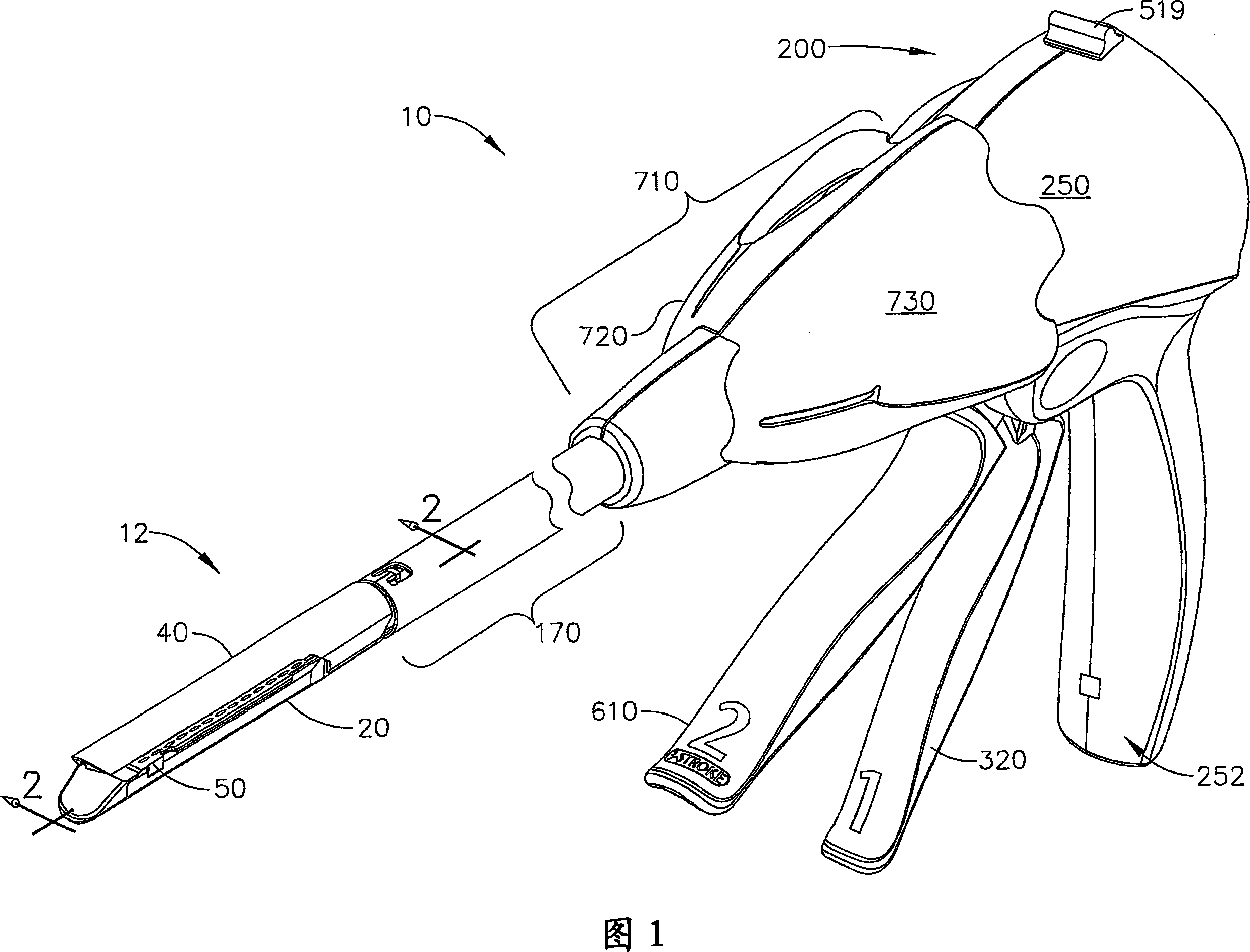
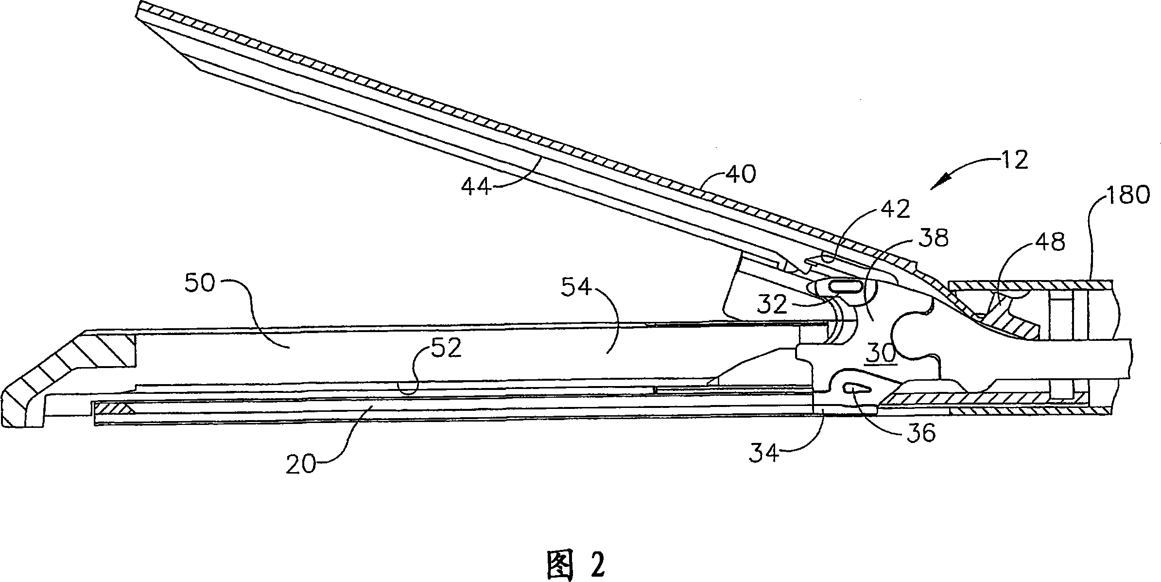
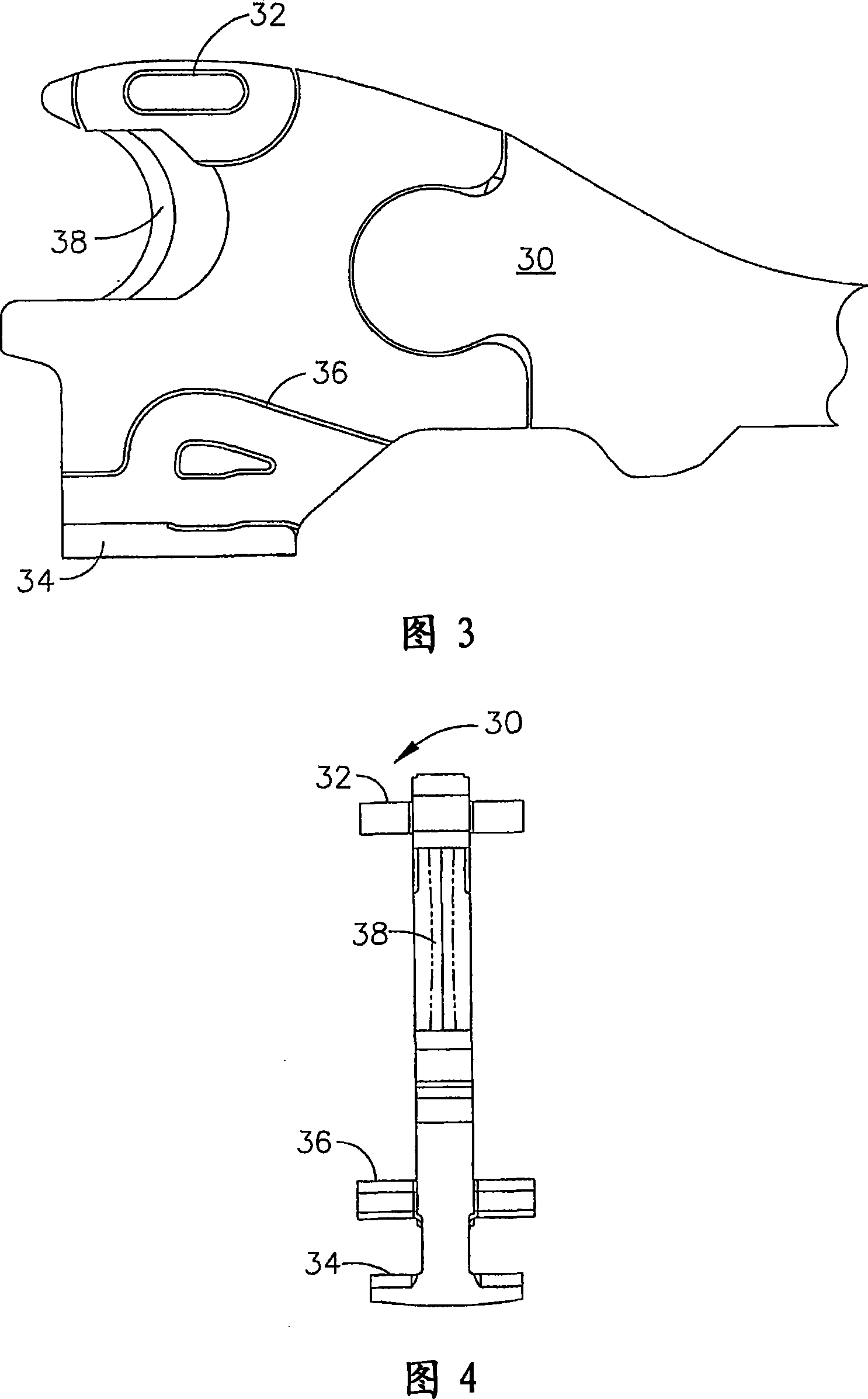
[0095] Turning to the drawings, in which like numerals represent like elements throughout, FIG. 1 illustrates a surgical stapling and cutting instrument 10 that is capable of practicing some of the unique advantages of the present invention. The surgical stapling and cutting instrument 10 includes an end effector 12 that is manually actuated by operation of a control member on a handle assembly 200 coupled thereto. A variety of different end effector configurations are known. One type of end effector 12 that may be used in various embodiments of the invention is shown in FIGS. 1 , 2 and 5-9. As shown in some of those figures, end effector 12 employs an E-beam firing mechanism ("firing bar") 30 that advantageously controls the spacing of end effector 12 . Various aspects of the E-beam firing mechanism are described in US Pat. No. 6,978,921 to Shelton IV et al., entitled Surgical Stapling Instrument Incorporating an E-Beam Firing Mechanism, the relevant parts of which are incor...


PUM


Abstract

A surgical cutting and fastening instrument that includes an elongate channel that is attached to a handle assembly by an elongate shaft assembly. The elongate channel is configured to receive a cartridge and has a pivotally translatable anvil attached thereto and a knife bar supported therein. The anvil may be selectively opened and closed by manipulating a closure trigger supported by the handle assembly. The knife bar may be distally advanced through the elongate channel by actuating a firing trigger that cooperates with a reversible rotary drive supported by the handle assembly. The knife bar may also be retracted to its starting position by actuating the firing trigger after the reversible rotary drive has been shifted to a retraction orientation.

Description

technical field [0001] The present invention relates generally to surgical instruments, and in particular to surgical cutting and fastening instruments. The invention may have application in conventional endoscopic and open surgical instrumentation as well as in robotic assisted surgery. Background technique [0002] Surgical staplers have been used in the prior art to simultaneously make a longitudinal incision in tissue and apply staple lines on opposite sides of the incision. The instrument generally includes a pair of cooperating jaw members capable of passing through the cannula channel if the instrument is to be used in endoscopic or laparoscopic applications. One of the jaw members receives a staple cartridge having at least two laterally spaced rows of staples. The other jaw member defines an anvil having staple-forming slots aligned with the rows of staples in the staple cartridge. The instrument includes a plurality of reciprocating wedges that, when driven dist...

Claims


Application Information

Patent Timeline
IPC IPC(8): A61B17/00A61B17/072A61B17/138A61B17/32A61B17/94
CPCA61B17/0682A61B17/07207A61B2017/00367A61B2017/07271A61B2017/07285A61B2017/00407A61B17/068A61B17/105A61B17/32B65B55/12
Inventor F·E·谢尔顿四世J·N·奥尔克克J·R·摩根J·S·斯韦兹E·L·蒂姆珀曼L·M·富吉卡瓦
Owner ETHICON ENDO SURGERY INC
Why Eureka
Try Eureka