Gear self-lubricating device for gear box

A gearbox and self-lubricating technology, which is applied in the direction of gear lubrication/cooling, can solve the problems of complex forced lubrication structure and poor splash lubrication effect, and achieve the effect of simple structure, simple installation and easy processing

A gearbox and self-lubricating technology, which is applied in the direction of gear lubrication/cooling, can solve the problems of complex forced lubrication structure and poor splash lubrication effect, and achieve the effect of simple structure, simple installation and easy processing

CN101101052AActive Publication Date: 2008-01-09西安航天泵业有限公司

Image

  • Gear self-lubricating device for gear box

Examples


Embodiment Construction

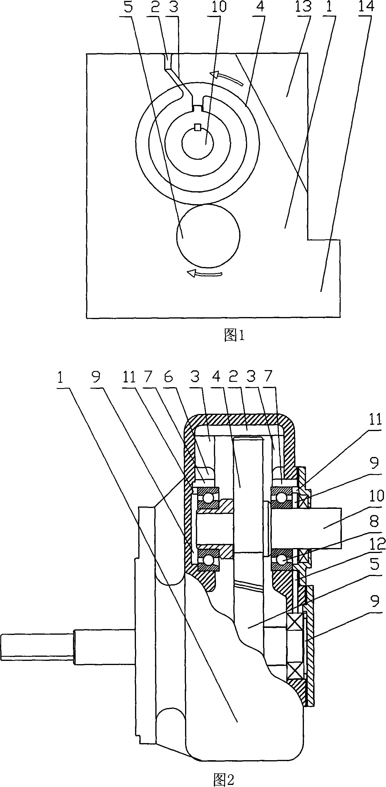
[0019] The specific structure of the present invention includes deflectors, guide grooves, oil inlets, lubricating oil chambers, and connecting grooves, wherein the deflectors include transverse deflectors arranged on the top surface of the inside of the gearbox casing and respectively arranged on the gear box There are two vertical baffles on the two side end surfaces inside the box, and the baffles are arranged horizontally on the upper gear bearing seat. The two ends of the horizontal baffles are respectively connected to the upper end of each vertical baffle. The lower end of the deflector is connected to the outer end of the diversion groove on the corresponding bearing, and the four lubricating oil chambers are respectively arranged between the bearing chambers of the bearings on both sides of the upper gear and the lower gear and the outer end surface of the bearing. The inner end opens to the upper end of the corresponding oil inlet, and the lower end of the oil inlet o...


PUM


Abstract

This invention relates bearing self- lubricating device for gearbox. It includes: guiding board arranged on the inner face of gear box; guiding groove laterally arranged on the bearing seat of upper gear; lubricating oil cavity arranged between bearing seat and outer face of bearing; oil inlet opening connecting lubricating oil cavity and guiding groove. The guiding board is composed of transverse guiding board and two standing guiding boards. Both ends of transverse guiding board connect with superior end of each standing guiding board respectively. The bottom of each standing guiding board connects with external end of guiding groove on corresponding bearing. The interior end of each guiding groove opens to superior end of corresponding oil inlet opening. The bottom of oil inlet opening opens to the top of corresponding lubricating oil cavity. This invention is simple and maintenance-free. The lubricating oil can be circular provided for a long time.

Description

technical field [0001] The invention relates to a bearing lubricating device, in particular to a gear box bearing lubricating device. Background technique [0002] There are two ways to supplement the lubricating oil of the existing gearbox bearings: one is the splash type, that is, the lubricating oil at the bottom of the gearbox is splashed around through the high-speed operation of the gear, and part of the splashed lubricating oil can replenish the lubricating oil for the bearing. One type of gearbox is simple in structure, but the replenishment of lubricating oil and lubricating effect are limited; the other is forced lubrication, that is, through a set of lubricating oil supply device, lubricating oil is supplied to the bearings at regular intervals or at any time. Oil filling is simple, but the gearbox structure is complicated. Contents of the invention [0003] The purpose of the present invention is to propose a gear box bearing self-lubricating device with good ...

Claims


Application Information

Patent Timeline
09 Jan 2008
Publication
CN101101052A
IPC
F16H57/04
Inventors
曾伟; 赵卫忠