
Camera motor

A motor and camera technology, applied in the field of camera motors with auto-focus structure, can solve the problems of time and power consumption, complex lens structure, and cost, and achieve the effect of low cost and simple focus structure

Inactive Publication Date: 2011-06-08
FU ZHUN PRECISION IND SHENZHEN +1
View PDF2 Cites 0 Cited by
  • Summary
  • Abstract
  • Description
  • Claims
  • Application Information

AI Technical Summary

Problems solved by technology

The focusing process of this lens consumes time and power, and the lens structure is complex and costly

Method used


Image

  • Camera motor
  • Camera motor
  • Camera motor

Examples


Embodiment Construction

[0015] The present invention will be further described below in conjunction with the embodiments with reference to the accompanying drawings.

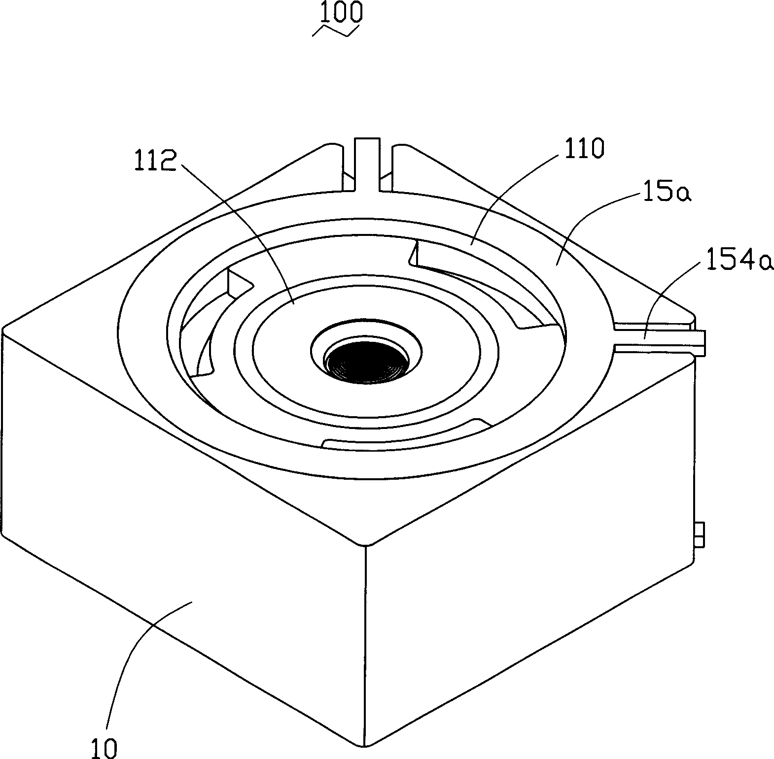
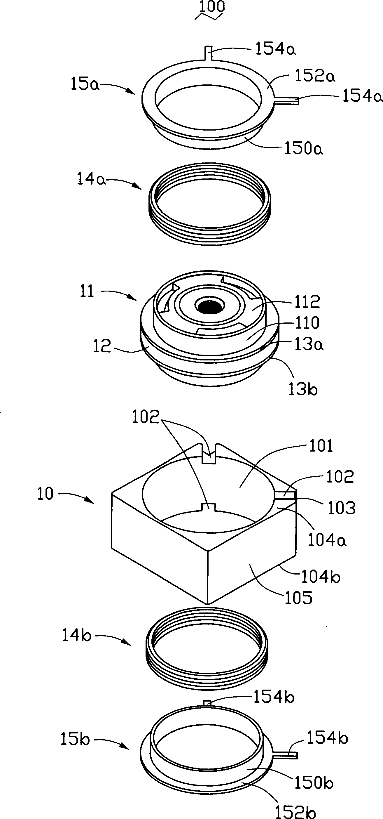
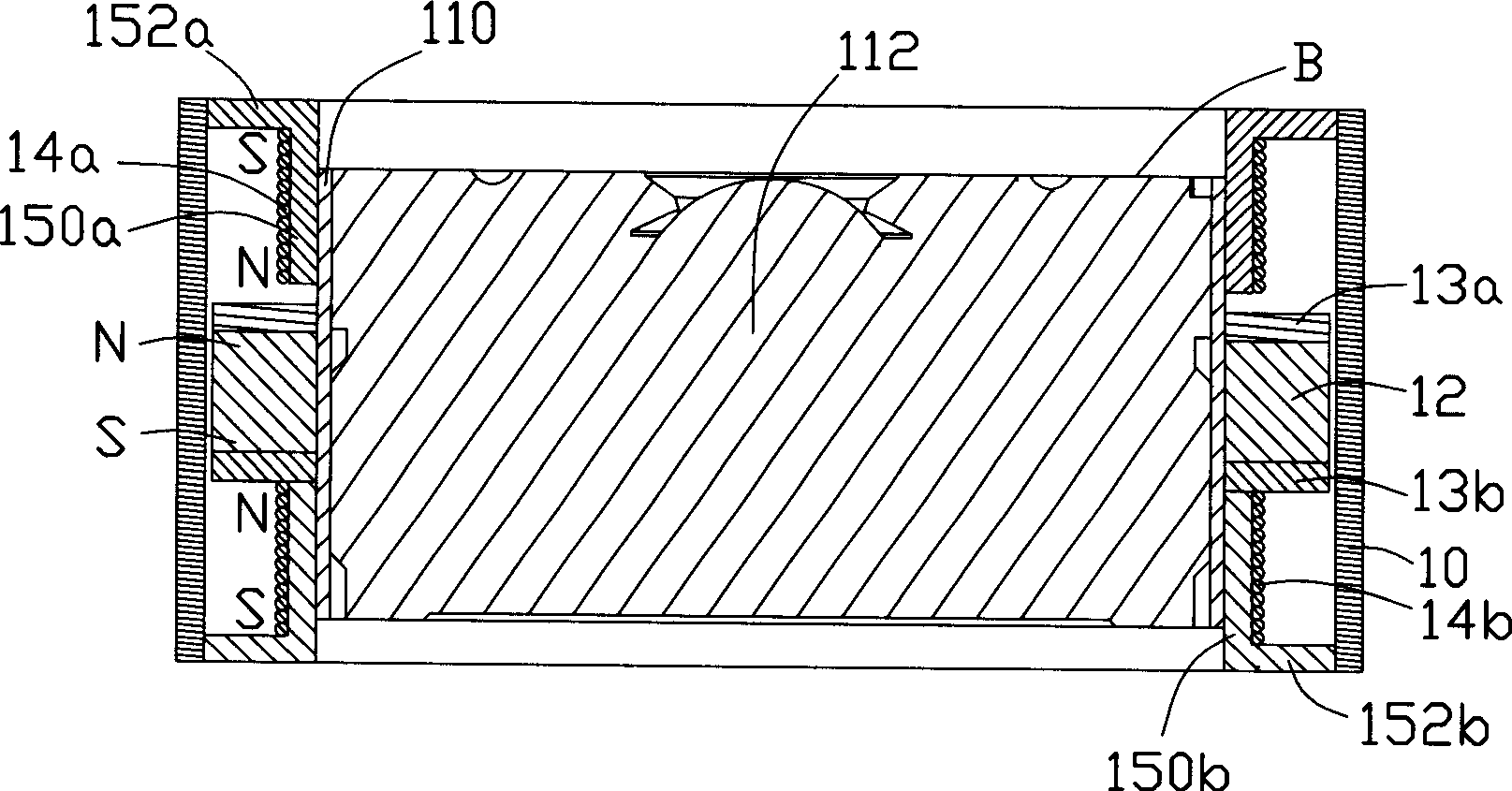
[0016] Please refer to figure 1 and figure 2 , the camera motor 100 of the present invention is an autofocus structure, which is applied in a digital camera, and can be in a far focus B (such as image 3 shown) and a near focal point A (such as Figure 4 As shown), it includes a casing 10, a lens group 11 placed in the casing 10, a permanent magnet 12 set on the lens group 11, upper and lower coils on both sides of the permanent magnet 12 Seats 15a, 15b, and upper and lower coils 14a, 14b respectively wound on the coil seats 15a, 15b in a certain direction.

[0017] The shell 10 is in the shape of a square column, and a cylindrical accommodating space 101 is formed inside to accommodate the lens group 11, the permanent magnet 12, and the upper and lower coil holders 15a, 15b surrounded by the coils 14a, 14b. Two grooves 102 are r...


PUM


Abstract

A camera motor comprises a lens group, a permanent magnet which is provided on the lens group and is capable of doing concertina motion together with the lens group, an upper and a lower loop bases which are respectively provided on two sides of the permanent magnet and an upper and a lower loops which are respectively wound around the upper and the lower loop bases; the lens group and the permanent magnet form as a whole; after the upper and lower loops are electrified and magnetic field is excited out, the upper and the lower loops and the permanent magnet interact with each other and drive the lens group to move between the perifocus and the over focus. Each loop includes a ring bottom surface and a ring wall extending from the ring bottom surface. The upper and the lower loops are wound on the ring wall. Two terminals for electrically connecting the loops to a power supply are respectively formed on the ring bottom surface. The camera motor also includes a casing. Slots for receiving the terminals are respectively formed on a top surface and a bottom surface of the casing. The ends of the upper and lower loops are respectively introduced by the terminals of the upper and the lower loop bases. The camera motor has the advantages of simple structure, miniaturization and low production cost.

Description

technical field [0001] The invention relates to a camera motor, in particular to a camera motor with an automatic focus structure. Background technique [0002] With the continuous development of digital technology, electronic technology is widely used in the field of cameras, digital imaging technology has developed rapidly, and cameras are becoming more and more intelligent. Especially in recent years, portable electronic devices such as mobile phones and PDAs (Personal Digital Assistants) are also rapidly developing towards high-performance and multi-functional directions, and the combination of digital cameras and portable electronic devices is also developing towards increasingly miniaturized directions. It is a development trend for groups to require thin, light and small designs. [0003] At present, most of the focusing structures of cameras use auto-focus technology. The auto-focus structure focuses on the target by checking the image on the image sensor. Such imag...

Claims


Application Information

Patent Timeline
Patent Type & Authority Patents(China)
IPC IPC(8): G02B7/04
Inventor 萧呈方黄晋兴洪健隆张金宏锺仁宏游丰檀
Owner FU ZHUN PRECISION IND SHENZHEN
Learn More