
Sectional type focusing lens module

A focus lens and segmented technology, which is applied in the field of segmented focus lens modules, can solve the problems of inconvenient assembly, increased lens module volume, and complex focusing structure of the lens module, etc., and achieves miniaturization and focusing structure. simple effect

Inactive Publication Date: 2014-03-26
HONG FU JIN PRECISION IND (SHENZHEN) CO LTD +1
View PDF3 Cites 0 Cited by
  • Summary
  • Abstract
  • Description
  • Claims
  • Application Information

AI Technical Summary

Problems solved by technology

[0003] At present, a considerable part of the focusing structure of the camera system adopts a segmented optical focusing structure. The existing segmented focusing lens structure is generally equipped with induction coils, magnetic elements and other structures to move the lens to focus, but this leads to lens modules. It is necessary to reserve space for induction coils, magnetic components, etc., which increases the size of the entire lens module. In addition, the focusing structure of the lens module is also relatively complicated and inconvenient to assemble.

Method used


Image

  • Sectional type focusing lens module
  • Sectional type focusing lens module
  • Sectional type focusing lens module

Examples


Embodiment approach 1

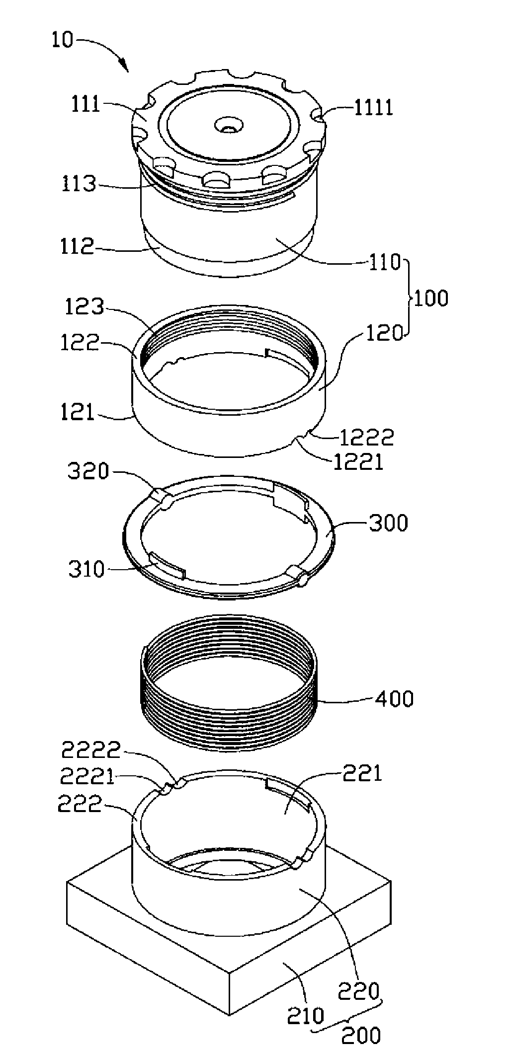
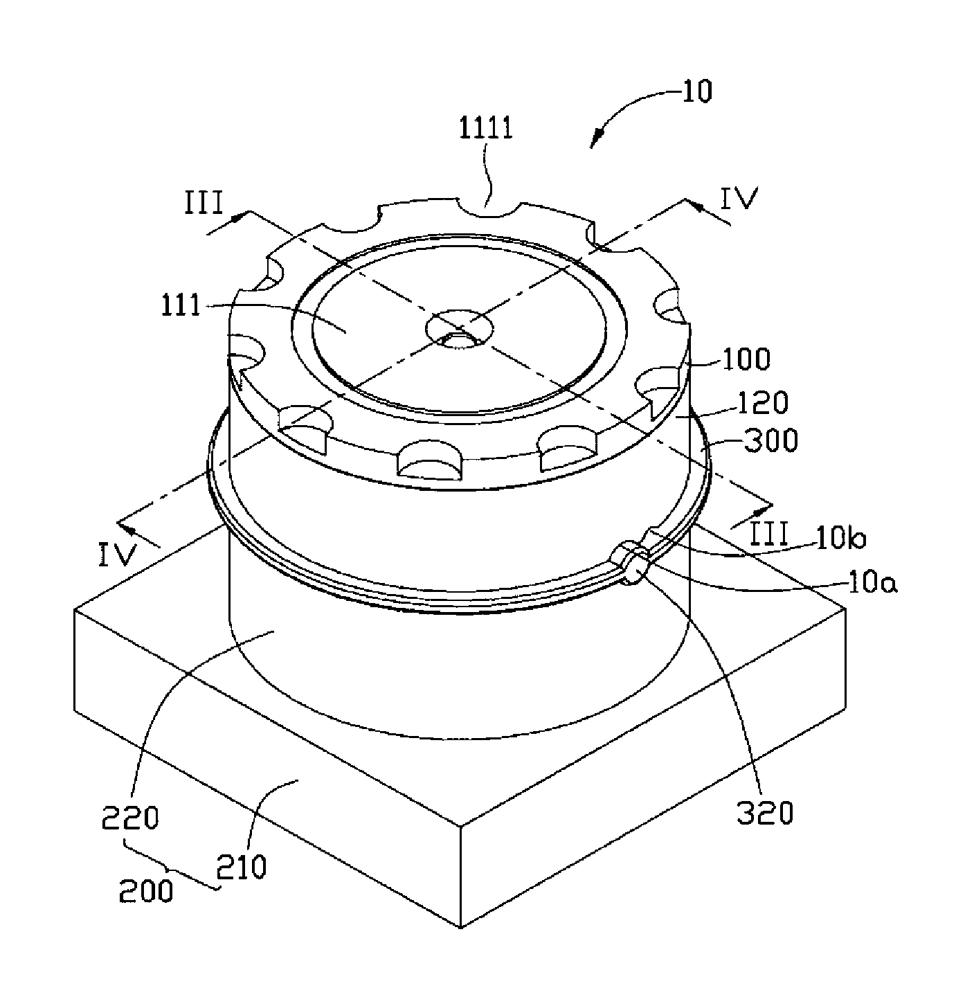
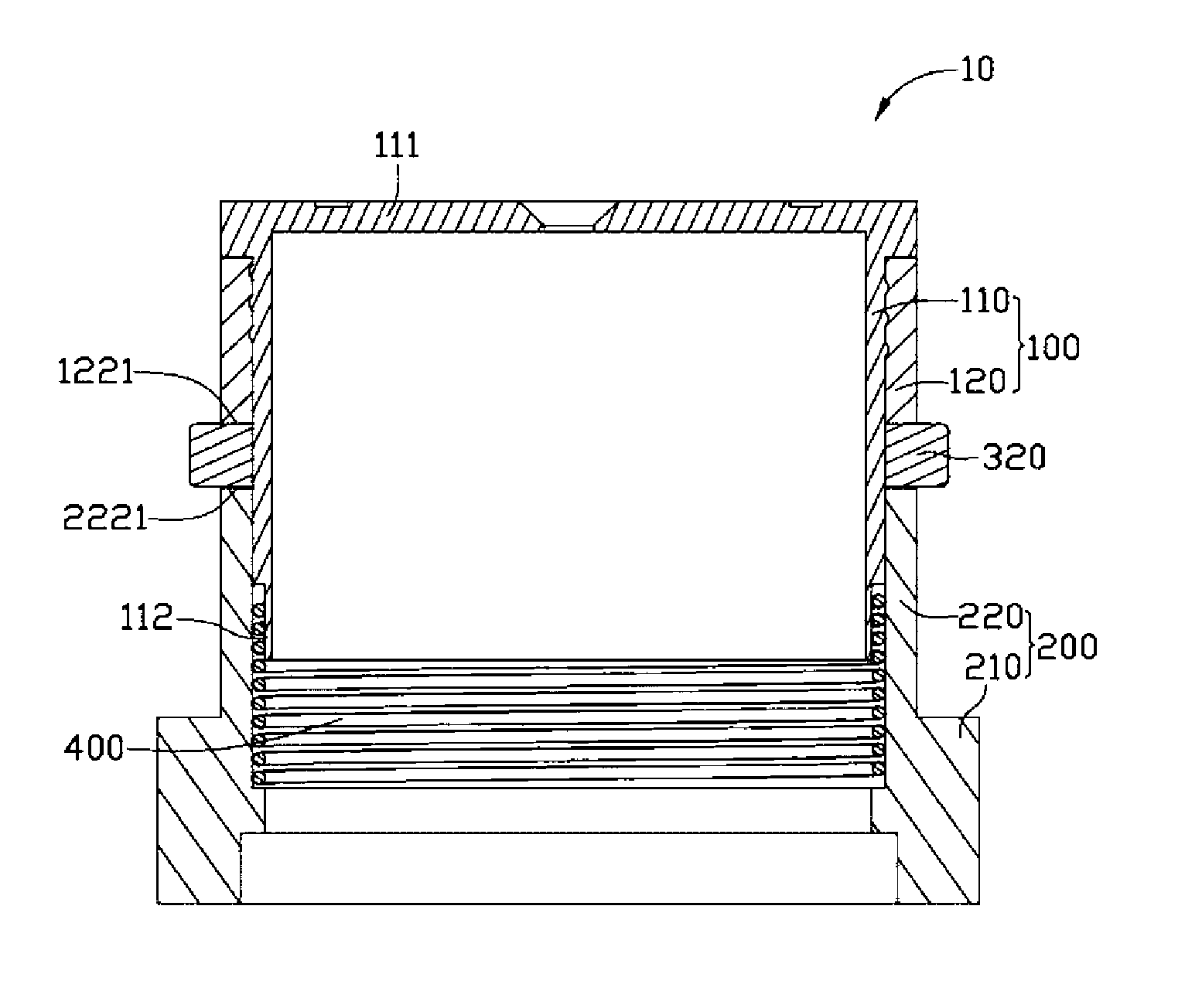
[0042] Please also refer to Figure 1 to Figure 4 , a segmented focus lens module 10 provided in the first embodiment of the present invention, which includes a lens barrel 100 , a lens mount 200 , a focus ring 300 and an elastic element 400 .

[0043] The lens barrel 100 includes an inner lens barrel 110 and an outer lens barrel 120 . The inner lens barrel 110 is in the shape of a cylinder, inside which accommodates elements such as lens groups, spacer rings and filters (not shown in the figure). The inner barrel 110 includes a first end 111 on the object side and a second end 112 on the image side. The first end 111 is in the shape of a disk, and its edge is evenly spaced with a plurality of grooves 1111, the grooves 1111 are used to facilitate the rotation of the inner lens barrel 110 to assemble the inner lens barrel 110 into the outer barrel 120. An external thread 113 is formed on a surface of the inner lens barrel 110 close to the first end 111 thereof.

[0044] The...

Embodiment approach 2

[0053] see Figure 5 The difference between the second embodiment and the first embodiment is that the top surface 222 of the mirror base 200 is provided with a third arc-shaped notch 2221 and a fourth arc-shaped notch 2222 with different depths in the direction of the optical axis. , the outer lens barrel 120' is not provided with an arc-shaped gap, and a protrusion 320' protrudes from the end surface of the focusing ring 300' opposite to the mirror base 200, and the protrusion 320' is in the shape of a half cylinder, and The axis is perpendicular to the optical axis.

[0054] When in use, turn the focus ring 300 ′, and the protrusion 320 ′ can slide between the third arc-shaped notch 2221 and the fourth arc-shaped notch 2222 formed on the top surface 222 of the mirror base 200 , and then drive the lens barrel 100 to move between two positions in the direction of the optical axis, thereby realizing split-end focusing of the lens module 20 .

Embodiment approach 3

[0056] see Image 6 The difference between the third embodiment and the first embodiment is that the bottom surface 121 of the outer lens barrel 120 is provided with a first arc-shaped notch 1221 and a second arc-shaped notch 1222 with different depths in the direction of the optical axis. The accommodating portion 220' of the mirror base 200 is not provided with an arc-shaped gap, and a protrusion 320'' protrudes from the end surface of the focus ring 300'' opposite to the outer lens barrel 120, and the protrusion 320'' It is in the shape of a half cylinder, and its axis is perpendicular to the optical axis.

[0057] When in use, turn the focusing ring 300 ″, the protrusion 320 ″ can slide between the first arc-shaped notch 1221 and the second arc-shaped notch 1222 formed on the outer lens barrel 120 , and then drive The lens barrel 100 moves between two positions in the direction of the optical axis, realizing split-end focusing of the lens module 30 .

[0058] Compared wi...


PUM


Abstract

The invention relates to a sectional type focusing lens module, which comprises a lens barrel, a lens seat, a focusing ring and an elastic element, wherein the lens barrel comprises a bottom surface being opposite to the lens seat; the lens seat comprises a top surface being opposite to the lens barrel; a first arc-shaped gap and a second arc-shaped gap are formed on at least one surface of the bottom surface of the lens barrel and the top surface of the lens seat; the depths of the first arc-shaped gap and the second arc-shaped gap along the direction of an optical axis are different; the focusing ring is arranged between the bottom surface of the lens barrel and the top surface of the lens seat, and a bulge is formed on the focusing ring; one end of the elastic element is fixed at the lens barrel, and the other end of the elastic element is fixed in the lens seat; the elastic element gives a pulling force to the lens barrel so as to clamp the focusing ring between the lens barrel and the lens seat; the focusing ring is rotated, and the bulge of the focusing ring can move between the first arc-shaped gap and the second arc-shaped gap; furthermore, the lens barrel is driven to move in the direction of the optical axis, the focusing structure is simple, and miniaturization of the lens module can be realized.

Description

technical field [0001] The invention relates to a segmented focusing lens module. Background technique [0002] With the continuous development of science and technology and modern industry, photographic products such as portable digital cameras and camera phones have been widely used. Therefore, the quality of the focus lens modules in these products has attracted more and more attention from the industry. [0003] At present, a considerable part of the focusing structure of the camera system adopts a segmented optical focusing structure. The existing segmented focusing lens structure is generally equipped with induction coils, magnetic elements and other structures to move the lens to focus, but this leads to lens modules. It is necessary to reserve accommodating space for induction coils, magnetic components, etc., which increases the volume of the entire lens module. In addition, the focusing structure of the lens module is also relatively complicated and inconvenient t...

Claims


Application Information

Patent Timeline
Patent Type & Authority Patents(China)
IPC IPC(8): G02B7/04
Inventor 陈彦均
Owner HONG FU JIN PRECISION IND (SHENZHEN) CO LTD
Learn More